Generate a High-Frequency Magnetic Field Using this Resonant Technique
Numerous test-and-measurement applications require a high-frequency magnetic field. Oftentimes, high field strength is needed. Examples of such applications include bio-medicine research on the effect of a magnetic field on living cells, scientific experiments, probe calibration, magnetic-field interference on electronic products, and much more.
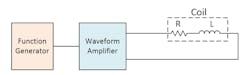
One the most common methods to generate a magnetic field is a Helmholtz coil pair. It produces a highly uniform magnetic field over a large open area. Figure 1 shows a depiction of a Helmholtz coil pair driven by a function generator amplifier. Although most Helmholtz coil magnetic fields are static or dc, increasingly more tests and experiments are requiring ac magnetic fields over a wide frequency range. Obtaining a high ac magnetic field faces a number of challenges that aren’t present with dc fields.
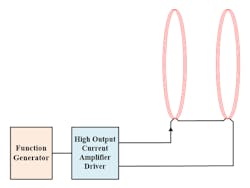
1. The Helmholtz coil pair is driven by a function generator amplifier to produce an ac magnetic field.
Achieving high magnetic fields in coils requires high electrical current. At dc or low frequency, the coil impedance is low and high current is fairly easy to obtain. The coil impedance is usually dominated by the coil’s parasitic resistance, which usually is small. Common power supplies or current sources are available to drive the coil at moderate to high current.
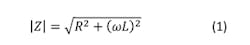
At high frequency, however, the magnetic coil impedance is increased proportionally to frequency. The impedance can be very large, often many times greater than the resistance. The coil impedance, Z, is proportional to the frequency and inductance (see Equation 1). At higher frequency, the impedance can be tens, hundreds, even thousands of times greater than the resistance. It’s difficult to obtain high current with such high impedance.
To calculate the coil current, use Equation 2. The current though the coil is inversely proportional to frequency. For a given voltage amplitude, the coil current decreases with increases in frequency.
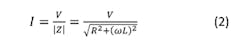
I is the coil current magnitude, V is the voltage amplitude, Z is the coil impedance, ω is the angular frequency (ω = 2πf), and L and R are the coil inductance and resistance, respectively. Equations 1 and 2 are for generic coils such as solenoids, Helmholtz coils, inductors, etc. For an ac Helmholtz coil pair, these two coils are connected in series, increasing the resistance by a factor of 2 and the inductance increasing slightly more than 2X (approximately 2.11X for most coil pairs).
In the case of low frequency or low inductance, or both, it’s straightforward to drive high ac current through the coil using a high-output current amplifier such as the TS250. The coil’s impedance is low enough whereby it can be driven by an amplifier directly (Fig. 2). The coil can be modeled (low-frequency model) as a parasitic resistor in series with an ideal inductor. The parasitic resistor resistance is generally small. In the case of Helmholtz coil, two coils connected in series are still modeled as a single coil, but 2X the inductance and resistance.
2. A high-current waveform amplifier is used to produce an ac magnetic field.
When the frequency is very high, though, the impedance of an electromagnet coil increases with frequency as discussed in Equation 1. When a high-frequency magnetic field is required, the coil impedance is very high. Thus, a high-voltage driver is needed to drive high current through the coil.
For example, at 100 kHz, the impedance of a 10-mH electromagnet coil will be 6283 Ω. To produce a high-enough magnetic field, high current is required. If 4 A is needed, the required voltage is more than 25 kV! It will be very difficult and not practical to design a driver than can produce 25 kV and 4 A with reactive power of 100 kW.
Resonant Technique
The direct-drive method shown in Fig. 1 is unable to drive high current into the magnetic coil at high frequency. Achieving a high-intensity and high-frequency magnetic field requires a resonance technique to reduce the impedance.
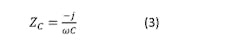
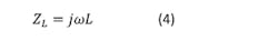
As illustrated in Figure 3, a capacitor is added in series with the coil. The coil and capacitor impedance are added together; their impedance is calculated in Equations 3 and 4. The capacitor impedance is negative and the coil impedance is positive. When the capacitance is correctly chosen, it acts like an impedance cancellation component. The capacitor therefore reduces the overall impedance.
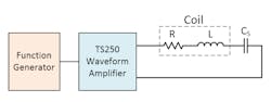
3. High field strength at high frequency is obtained by using a resonance capacitor to cancel the coil impedance.
In fact, at resonant frequency, the impedance of the capacitance completely cancels the impedance of the inductance. In other words, the coil and capacitor impedances are equal in value but opposite in polarity. At resonance, the waveform amplifier driver only “sees” the coil’s resistance. With only a small level of resistance left in the system, the high-output current amplifier now can drive very high current through the Helmholtz coil or solenoid, even at high frequency. The resonant method allows the function generator amplifier to generate a high magnetic field.
Let’s use an example to further understand how the resonant capacitor can cancel impedance. The coil or solenoid in Figure 4 is 2 mH and the desired frequency is 200 kHz. If the frequency is at resonant, the voltage across the coil is +2.5 kV, and the voltage across the series capacitor is −2.5 kV. Consequently, the total net voltage is zero across the inductor and capacitor combination. The LC, therefore, is essentially a short-circuit at resonant frequency.
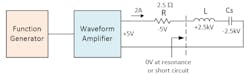
4. Impedance is cancelled by the capacitor.
The TS250 Waveform Amplifier only “sees” the coil’s parasitic resistance as a load. Generally, the magnetic coil resistance is small, which enables the amplifier to drive high current through the solenoid coil with low voltage. The voltage across the coil is still very large. Interesting to note the voltage sum in a closed loop is 0 V governed by the Kirchhoff’s Voltage Law.
The resonant technique is the most practical way to generate a strong high-frequency magnetic field. The only drawback is that it operates over a narrow frequency range near the resonance. To be able to produce an electromagnetic field over wider frequency range, the user needs to change the capacitor multiple times. Usually, a perfect resonant isn’t needed—you just need the capacitor to cancel enough impedance to enable the driver to drive enough current. This allows for operation over a slightly wider frequency window.
Calculate Resonant Capacitance
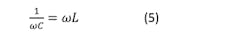
The resonant condition is when the capacitor reactance is equal in magnitude to the inductor reactance, but opposite polarity as detailed above. Therefore calculate the series resonance capacitance such that the capacitor’s reactance is the same as coil reactance at a given resonant frequency.

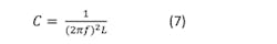
Using the above example for 2-mH Helmholtz coils and 200-kHz operation, the series capacitance is calculated as 317 pF.
Choose a high-Q (low ESR) and low-ESL (electrostatic inductance) resonance capacitor to cancel the impedance. The capacitor needs to be rated for high voltage. The voltage rating is calculated by the following:
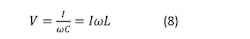
where I is the peak current.
Using the above example, the voltage rating must be at least 2.5 kV (V = 1 A * 2512 Ω = 2512 V). Add additional voltage-rating margin if higher current is used.
Maximum Frequency Practical Limitation
The resonant technique uses a series resonance capacitor to cancel out the coil reactance; theoretically it will reduce the impedance to just the parasitic resistance. In theory, the frequency and magnetic-field strength can be very high. However, there are some practical limitations.
The first limitation is the capacitor voltage rating. Equation 8 is used to calculate the capacitor voltage rating for a given coil current, inductance, and frequency. If the required voltage is less than 10 kV, there are generally plenty of capacitors to choose from. If the voltage is higher than 10 kV, fewer capacitors are available. As a rule of thumb, the maximum practical voltage is about 50 kV. If higher than 50 kV, other practical challenges such as electrical arc will arise.
The second practical limitation is the capacitance. At higher frequency, the capacitance value is reduced. Generally, a capacitance of 100 pF or larger is recommended. Capacitance down to 10 pF is possible, but parasitic capacitance from the connection wires and the coil itself start to take effect.
Coil Design
The magnetic field in solenoid coils is given in Equation-9 and Equation-10 for Helmholtz coil pair.
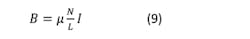
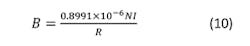
B is the magnetic field, µ is the permeability, N is the number of turns, L is the length, I is the current, and R is the coil radius.
A high magnetic field in an electromagnetic coil can be achieved in various ways: increase the number of turns, increase current, increase the permeability, and decrease the radius.
Increase the Number of Turns (N)
In electromagnetic coils such as solenoids, inductors, and Helmholtz coils, the magnetic field is proportional to the number of turns. Increasing the number of turns will result in a higher magnetic field. However, it also increases the inductance and parasitic capacitance. As discussed above, higher inductance isn’t desirable and will require higher capacitor voltage.
Generally, the inductance is proportional to the square (power of two) of the number of turns. For a high-frequency magnetic field, it’s recommended to reduce the number of turns, but increase the current. This way, you can obtain the same field intensity, but lower the inductance and lower the capacitor voltage rating.
Self-Resonant
Increasing the number of turns also raises the parasitic capacitance CP (Fig. 5). Higher CP lowers the coil’s self-resonant frequency. In general, the frequency of operation should be 2-5 times lower than the self-resonant frequency (see table below). Lower self-resonant frequency due to CP will limit the maximum coil working frequency.

5. Inductor model with parasitic R and CP.
Reduce Coil Radius
Typically, reducing the coil radius doesn’t change the magnetic field for long solenoids, but it will reduce the inductance and CP. Reducing CP will increase the self-resonant frequency. Therefore, when designing a coil, keep the radius as small as possible.
In the case of Helmholtz coil, reducing the radius will have three positive benefits. A smaller radius will increase the magnetic field, increase the self-resonant frequency, and reduce the inductance. Lower inductance is paramount, as discussed in the “Maximum Frequency Practical Limitation” section above. Again, keep the radius as small as possible.
Increase the Permeability
For scientific experiments other than an air core coil, a magnetic core can be inserted into the coil to increase the magnetic field. Not all core materials are equal. Some magnetic materials have high permeability, but in low-frequency and low-saturation applications. Choose a magnetic material for the rate of frequency of operation that doesn’t saturate at the desired magnetic-field strength. The magnetic core also increases the inductance.
In summary, use the follow criteria to design AC magnetic coils:
- The coil must be rated for the current and power (heating) handling capability.
-Low resistance to reduce heating and allow for higher current.
-Consider resistance increases at high frequency due to skin effect.
- Consider reducing the number of turns, but increasing the current to lower the inductance.
- Make sure the coil self-resonant frequency is 2-5X higher than the working frequency.
- Keep the coil radius as small as possible to reduce resistance, inductance, and parasitic capacitance.
- If desired, choose a magnetic core with high permeability but rated for the working frequency and high saturation field.
- Design the coil to handle high voltage (avoid electrical arc).
Simulation Results
Using the inductor model in Fig. 5, a coil is driven by a ±1V sine wave. In this example, L = 1 mH; CP = 125 pF; R = 0.5 Ω; Cs = 470 pF; and the working frequency is same as the series resonant frequency of 206 kHz. The coil’s self-resonant frequency is 450 kHz.
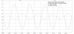
6. The inductor is operating at a series resonant of 206 kHz. At about half the self-resonant frequency, the inductor current is reduced due to current “leak” in the parasitic capacitor CP.
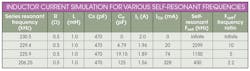
Figure 6 shows the inductor current. The peak inductor current is 1.56 A and the peak CP current is 328 mA 180 deg. out-of-phase. Contrast that with the 2299-kHz self-resonant in the table—the peak inductor current is 1.96 A with only 20-mA CP current. Therefore, when the working series-resonant frequency is close to the self-resonant frequency, it reduces the inductor current. Looking at the table’s simulation data, it’s acceptable to operate the coil up to about half of the self-resonant frequency. At this frequency, the coil current is reduced by about 25%. It’s not recommended that the working series resonant frequency be higher than half the self-resonant frequency.
Caution: Potential Electrical Shock
The high-current electromagnetic coil discussed above can store enough energy to become an electrical shock hazard. Make sure all electrical connections are insulated with high-voltage insulators. Wires must be rated for voltages discussed earlier. Always disable the amplifier output before connecting or disconnecting the coil and capacitor.
Conclusion
A high-current amplifier driver is needed to produce a high ac magnetic field. When a high-frequency magnetic field is required, the resonant technique will reduce the coil impedance and allow for high current to drive the coil with a low-voltage function generator amplifier.
The resonant technique is the most powerful way to generate a high-frequency ac field. At high frequency, the practical limitation is the availability of high-voltage capacitors. Another limitation is the magnetic coil self-resonant frequency. Furthermore, the self-resonant frequency should be 2-5 times higher than the working resonant frequency.
References:

About the Author
KC Yang
Product Marketing Engineer
KC Yang is a product marketing engineer at Accel Instruments, which specializes in high-frequency and high-current amplifiers for general lab bench testing. He received a Master of Science in electrical engineering from University of California, San Diego, and a Bachelor of Science in physics from Washington State University. He has published numerous application notes and article.
Comment About the Article
To join the conversation, and become an exclusive member of Electronic Design, create an account today!

Leaders relevant to this article: