High-Speed Data Converters Make Direct-Sampling Receivers Practical

Download this article in PDF format.
Communications receiver architecture has evolved slowly over the years. The most common and successful configuration is the superheterodyne architecture, which translates the incoming signal to a lower (or higher) intermediate frequency (IF), where bandwidth and gain can be controlled. Since then, newer digital modulation modes have fostered some new architectures. The most recent configuration is the direct-sampling architecture that has been enabled by super-fast analog-to-digital converters (ADCs).
Sponsored Resources:
- Optimize Your RF Sampling ADC Receiver Performance with the Frequency & Sample Rate Planning Calculator
- Maximize your design with the industry's widest bandwidth
- Be the office-expert on high-speed data converters
Receiver Architectures in Review
The earliest receiver architecture was of the tuned radio frequency (TRF) type with multiple amplifiers, each tuned to the desired frequency. Then the regenerative receiver came along and added feedback to an RF stage that improved gain and selectivity.
Both of those types went away quickly once Edwin Armstrong invented the flexible superheterodyne (Fig. 1a). A low-noise amplifier (LNA) provides input gain. The incoming signal is mixed with a local-oscillator (LO) signal in a mixer to downconvert the incoming signal to a lower IF where a fixed bandwidth is established with a bandpass filter (BPF) along with high-gain IF amplifiers just prior demodulation. The superhet is still widely used. Dual-conversion and triple-conversion versions solve the image and selectivity problems that occur.
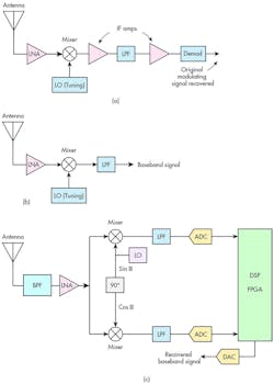
1. Standard receiver architectures include superheterodyne (a), direct conversion (b), and I and Q direct conversion (c).
An interesting new form known as a direct-conversion receiver came along next (Fig. 1b). The local oscillator is set to the incoming signal frequency so that the mixer and low-pass filter (LPF) convert the signal directly to original the baseband modulating signal.
With the newer digital modulation modes (like QAM) now dominant, a new architecture emerged. It’s a variant of the direct-conversion receiver (Fig. 1c). The local oscillator is at the signal frequency but split by 90 degrees between two mixers. This results in two baseband outputs—an in-phase (I) component and a quadrature (Q) component are filtered in LPFs. These two signal paths are digitized in ADCs that send the binary form to a digital signal processor (DSP) or field-programmable gate array (FPGA) where demodulation takes place. The I and Q signals preserve amplitude and phase information that’s needed to recover the original modulating signal.
The newest form of receiver architecture is direct sampling (Fig. 2). The incoming signal is filtered to provide some selectivity and amplified in a low-noise amplifier (LNA). From there, it’s directly sampled by a fast ADC into digital form for the DSP or FPGA that does additional filtering and demodulation. The main factor making this configuration work are the newer ADCs that are fast enough to sample the incoming frequencies. The bulk of communications today takes place in the UHF and microwave spectrum from 300 MHz to 6 GHz. It’s taken a while for semiconductor vendors to make a faster ADC.
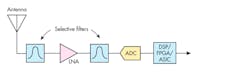
2. Shown is a direct-sampling receiver.
Both direct-conversion and direct-sampling receivers are what we call software-defined radios (SDRs). This is where most of the demodulation, filtering, and other processes take place inside of a DSP, FPGA, or ASIC.
Aliasing and Undersampling
Remember the Nyquist rule that says that an ADC must sample the input by a factor of two or more times the highest frequency content to retain that original information and to prevent aliasing? That process is known as oversampling. For example, a 2.5-GHz signal must be sampled at a rate higher than 5 GHz.
While oversampling is the usually preferred mode for fast ADCs in a digital receiver, undersampling also can be useful. If you sample at a rate less than the 2X Nyquist rate, you are undersampling. This creates an alias. The alias is a new signal with a frequency that’s the difference between the sampling rate fs and the input signal being sampled fi.
falias = fs – fi
This is the output that you would get if you put the undersampled data stream back through a digital-to-analog converter (DAC).
To eliminate the alias problem, it’s customary to put a low-pass filter ahead of an ADC to eliminate signals that are half the sampling rate or more.
While aliasing is a problem in some oversampling applications, it can be utilized positively in others. For example, you can use it as a type of downconverter to create a lower IF, where the signal may be easier to process. Selecting a sampling rate can be tricky in order to achieve the desired result. One solution is mentioned at the end of this article.
A Representative Fast ADC
One device up to this job is Texas Instruments’ ADC12DL3200, which can be configured as a 6.4-Gsample/s single-channel converter or two 3.2-Gsample/s converters. Each ADC is a 12-bit converter with LVDS Interface. The device can handle frequencies up to abut 10 GHz, making it useful for receivers in the many existing cellular bands as well as the L, S, C, and X microwave bands. This ADC has an exceptional bandwidth of 8 GHz and a noise floor of −154.3 dBFS/Hz. Versions with a JESD204B interface are available in lieu of the LVDS.
Figure 3 shows one possible receiver configuration. Note that a balun is used to translate the unbalanced input into a differential input for the ADC. The LVDS connections to the DSP or FPGA are also differential lines. The LMK04832 is a PLL clock synthesizer and distributor.
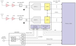
3. Here, a direct-sampling software-defined radio is using TI’s 12-bit, 6.4-Gsample/s ADC12DL3200 with LVDS.
Designing with the ADC12DL3200 is relatively easy. It eliminates a considerable amount of previously needed receiver circuits like mixers, oscillators, plus additional filtering and amplification.
What More Do You Want to Know?
If you’re looking for more information on the ADC12DL3200 and its application, go to Texas Instruments’ High-Speed Signal Chain University. It’s a portal to relevant training material on high-speed data converters, including topics related to RF sampling converters, JESD204B SerDes standard, and related RF fundamentals. Whether you’re using oversampling or undersampling, you can optimize your RF sampling ADC receiver performance with TI’s Frequency & Sample Rate Planning Calculator. A related video explains in detail the concept of frequency planning and shows how to use TI tools for frequency planning, RF filter estimation, and decimation filter spur calculation. The links below will take you right to this information.
Sponsored Resources:
About the Author

Lou Frenzel
Technical Contributing Editor
Lou Frenzel is a Contributing Technology Editor for Electronic Design Magazine where he writes articles and the blog Communique and other online material on the wireless, networking, and communications sectors. Lou interviews executives and engineers, attends conferences, and researches multiple areas. Lou has been writing in some capacity for ED since 2000.
Lou has 25+ years experience in the electronics industry as an engineer and manager. He has held VP level positions with Heathkit, McGraw Hill, and has 9 years of college teaching experience. Lou holds a bachelor’s degree from the University of Houston and a master’s degree from the University of Maryland. He is author of 28 books on computer and electronic subjects and lives in Bulverde, TX with his wife Joan. His website is www.loufrenzel.com.
Comment About the Article
To join the conversation, and become an exclusive member of Electronic Design, create an account today!

Leaders relevant to this article: