Download this article in PDF format.
All too often, the overall performance of an electronic design isn’t limited by technology constraints, but rather ultimately boils down to a problem of heat dissipation. With the exception of superconductors, the operation of all electrical and electronic equipment results in some power loss, which is inevitably dissipated as heat.
Accepting this fact, equipment designers need to consider how that heat will affect the performance of their design and how to remove it from their system. In doing so, they can ensure that their design continues to operate correctly, with no damaging effects on individual component parts. As systems grow more complex, with rapidly increasing densities, the thermal management of your system becomes a major design consideration.
In many instances, heat can be conducted away from critical components, through the circuit board and case, and dissipated to the surrounding air. For larger systems, especially computers, servers and similar rack-mount equipment, where the combination of conduction and natural convection cooling isn’t sufficient, fans are often needed to provide forced-air cooling.
Once a designer reaches this conclusion, the next question is, “What sort of fan do I need?” followed by “What size does the fan need to be and what other criteria are important in specifying the right fan for my application?” As with most things in life, and particularly in engineering, there’s a process to go through to arrive at answers to these questions. Here are a few simple steps to help with that process:
Step 1: Understand where and how much heat is being generated
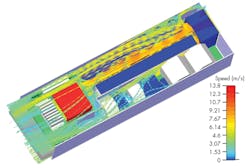
Before you can begin the process of selecting a fan, you must understand how much heat your system is generating. Components such as microcontrollers, processors, FPGAs, and MOSFETs are often the heaviest consumers of power and, hence, the prime culprits for significant heat dissipation. These components can create hot spots within the system. However, it’s possible to model the resulting thermal profile, either with a number of distributed thermocouples or more accurately using computational fluid dynamics (CFD) (Fig.1).
1. Thermal profiling of a design will ensure hot spots are located within the design.
Step 2: Determine the airflow needed to keep the temperature rise in check
Component performance and reliability can be dramatically impaired when operating at higher temperatures. Even though a device will normally have a specified operating temperature range, it’s often desirable to keep the actual operating temperature well below the upper limit of that range. Therefore, to determine what airflow (Q) will be required to ensure that component temperatures stay within an acceptable range, we first need to determine an allowable temperature rise (ΔT).
In addition to the allowable ΔT, the full formula used to calculate Q also involves the heat absorbed by the air (q) as well as the specific heat of air (Cp) and the density of air (ρ), which both vary with temperature. If we substitute for these at a defined temperature, of say 26°C, then the equations become a little simpler:
Q = 0.05 x q/ΔT (for Q in cubic meters per minute, or CMM)
or
Q = 1.76 x q/ΔT (for Q in cubic feet per minute, or CFM)
Step 3: Find a fan that meets the airflow requirement
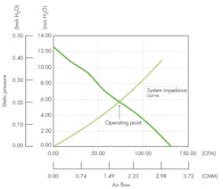
Next, we need to understand the airflow impedance of our system. Normally, fan manufacturers specify airflow for a given static pressure, i.e. the atmospheric pressure in the enclosure when there’s no air flow. As airflow varies inversely with static pressure, manufacturers typically present the information using graphs.
Airflow impedance, also referred to as back pressure, is the drop in air pressure from inlet to outlet. This difference can be measured for different rates of air flow using pressure sensors or by placing the system in an air chamber. By plotting the airflow impedance of a system on the same graph that shows the variation of airflow against static pressure, we can arrive at an operating point defined by the intersection of these two curves (Fig. 2).
2. Plotting the airflow impedance of a system on the same graph as static pressure makes it possible to more accurately specify the fan required.
For many designs, characterizing system impedance by measuring the back pressure may not be possible or considered a step too far. A potentially more practical and simplified solution would be to over-specify the fan. For example, if the airflow calculated is 50 CFM with zero back pressure, over-specifying the fan such that it produces a maximum of 100 CFM with the intention of operating it at 75 CFM would provide a good margin of error. It will also provide some headroom for increasing airflow during operation.
Ideally, cooling requirements should be considered early in the design process. Therefore, critical heat-dissipating components could be optimally placed to benefit from cooling air flow, while other bulky components would be positioned to avoid blocking air inlets or outlets.
Step 4: Choosing the type of fan
The most common fan type is the axial fan. These can provide high airflow and are ideal for systems with relatively low static pressure since the air enters and leaves the fan in the same direction. Centrifugal fans expel air in a different direction, which has the effect of compressing the air. This may be helpful to overcome the higher static pressures encountered in some systems. Typically, though, such fans are only suitable for lower airflow requirements.
Step 5: Final considerations
Fan noise, both acoustic and electrical, and speed control are other factors a designer may need to consider. Axial fans, especially larger diameter fans, will normally be quieter in operation than smaller fans that have to run faster to achieve the same airflow, and will certainly be quieter than a comparable centrifugal or blower-type fan.
While some cooling fans may be continually operated, today it’s more likely that temperature monitoring will be employed so that a fan is only turned on when required. Even more likely is that its speed is adjusted to reach the required level of cooling.
Speed control can be achieved by varying the duty cycle of the voltage applied to the fan’s motor, using pulse-width modulation (PWM). This approach is used in modern dc axial fans, such as the CFM series from CUI. Models like the CFM-60 series offer sophisticated controls like sensors to measure fan speed. By detecting rotation, they can react if the fan stalls by signaling a fault condition to the system, and even attempt to restart the fan.
Finally, fan motors can give rise to electromagnetic interference (EMI). While this is inherent in all dc fans, the EMI is typically limited to conducted EMI in the power leads, which can usually be suppressed using ferrite beads or shielding.
Like it or not, unwanted heat will always be a challenge to most electronic designs. However, the effective implementation of a cooling fan can allow an electrical system to operate optimally while also improving the design’s longevity.
To learn more, visit http://www.cui.com/catalog/components/thermal-management.
About the Author
Jeff Smoot
VP of Engineering, CUI Devices
Since joining CUI Devices in 2004, Jeff Smoot has revitalized the company's Quality and Engineering departments with an emphasis on developing, supporting, and bringing products to market. With a focus on the customer’s success, he also spearheaded the establishment of an Application Engineering team to provide enhanced in-the-field and online design and technical support to engineers during the design process.
Prior to CUI, Jeff operated as a manufacturing engineer for Fiskar's Gerber Legendary Blade Division, focusing on the NPI of the company's knives and multi-tools.
Jeff holds a Bachelor’s of Science in mechanical engineering from Montana State University.


