Microcontroller Generates Chaotic Lorenz Signals
This file type includes high resolution graphics and schematics when applicable.
Chaotic systems are interesting for a variety of reasons, including their relevance to meteorology, physics, and engineering. A well-known chaotic system is the Lorenz system, described by non-linear differential equations:
du/dt = σ(v – u)
dv/dt = ru –v – 20uw
dw/dt = 5uv –bw
where u, v, and w are the time-dependent variables of the chaotic system and r, b, and σ are the constant parameters that can be adjusted to alter the overall behavior of the system.1
This Idea for Design solves the Lorenz chaotic system numerically in a microcontroller, combining a novel approach to generating chaotic signals with the convenience of a simulation and an ability to synthesize real signals when desired.
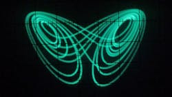
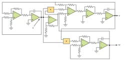
The analog circuit implements and solves the differential equations of the Lorenz system and generates signals u, v, and w of the system, which then can be observed on an oscilloscope to examine the system’s chaotic behavior (Fig. 1). These signals can be used to encode an information signal for secure transmission.2
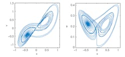
If real signals aren’t required, the Lorenz system may be simulated on a computer using one of several numerical methods available for solving systems of differential equations. In the results of a computer simulation with Matlab, these plots are similar to patterns one would observe on an oscilloscope connected to the output of the analog circuit (Fig. 2).
The simulation provides for easy modification of the parameters and initial conditions, which affect the overall behavior of the system. Furthermore, the simulation avoids the difficulties encountered with the analog circuit, as there is no limitation to the range of signals due to amplifier saturation, nor is there any compromise or consideration required for the proper selection of component values.
In this solution, we use a microcontroller to find the numerical solutions for u, v, and w, and then pass the results to the pulse-width-modulation (PWM) module of the microcontroller to adjust a duty cycle of one, two, or three pulse trains, depending on the number of PWM signals generated by a given microcontroller. Finally, the PWM signals are low-pass filtered to generate analog signals with behavior that is similar to that observed at the output of the analog circuit for the Lorenz system.
This approach provides a convenient way to generate a set of signals for demonstration and application to the study of chaos systems. In addition, parameters of the system can be easily modified and reprogrammed into the microcontroller to observe their effect on the overall system behavior.
The implementation of this approach is straightforward. The Lorenz system is solved with Euler’s method, which has been programmed into a PIC18F2520 microcontroller.3 Parameters r, b, and σ were set to 45, 4, and 16, respectively. Since the range for the numerical solution of u, v, and w is real floating-point numbers, the results need to be offset and scaled prior to being cast as unsigned integers and used in setting the PWM duty cycle.
Figure 3 shows the oscilloscope traces for the output of the low-pass filters used to convert the PWM into analog. Figure 4 shows the typical implementation of the low-pass filter used to filter each PWM signal. Since the PIC18F2520 has only two PWM outputs, the PIC must be reprogrammed accordingly to view each pair of signals on the oscilloscope.
The microcontroller code below is written specifically for the PIC18F2520 using the CCS compiler. It can be easily modified to work with other PIC microcontrollers or other popular microcontrollers, such as the Arduino.
#include <18F2520.h> #fuses HS,NOWDT,NOPROTECT,NOLVP, NOPBADEN #use delay(clock=20000000) #include/* Solve the Lorenz non-linear system with Euler's method. Write the output to the PWM on RC1 and RC2 of the PIC. */ /*~~~~~~~~~~~~~~~~~~~ VARIABLES ~~~~~~~~~~~~~~~~~~~~~~~~~~~*/ float SIGMA = 16.0; float R = 45.0; float B = 4.0; float Ts = 0.001; /*~~~~~~~~~~~~~~~~ FUNCTION PROTOTYPES ~~~~~~~~~~~~~~~~~~~~*/ void initPIC(void); // set up the PIC /*~~~~~~~~~~~~~~~~ MAIN ROUTINE ~~~~~~~~~~~~~~~~~~~~*/ void main() { float x_prev = 0.1; // initial conditions float y_prev = 0.1; float z_prev = 0.1; float x,y,z; // variables in the Lorenz system int16 xOut, yOut, zOut; // int16 values that are passed to the PWM // initialize the PIC MCU initPIC(); while(TRUE) //while1.0 { // Euler's method. x = x_prev + Ts*(SIGMA*y_prev-SIGMA*x_prev); y = y_prev + Ts*(R*x_prev - y_prev - (x_prev*z_prev)); z = z_prev + Ts*(x_prev*y_prev - B*z_prev); x_prev = x; y_prev = y; z_prev = z; // scale and offset the before passing to the PWM xOut = (int16) (4.48*x + 134.3); yOut = (int16) 3.0*(y+50.0); zOut = (int16) (3.09*z -0.22); // set the PWM duty cycle here //set_pwm1_duty(yOut); // comment this line, and uncomment next line, set_pwm1_duty(zOut); // if desired, to see the signal on the o'scope set_pwm2_duty(xOut); delay_ms(1); // change this as desired to speed up or slow // down the trace on the oscilloscope } }// end of main /*~~~~~~~~~~~~~~~ FUNCTION DEFINES ~~~~~~~~~~~~~~~~~~~~~*/ void initPIC(void) { // for PWM setup setup_ccp1(CCP_PWM); // config CCP1 (RC2) as PWM setup_ccp2(CCP_PWM); // config CCP2 (RC1) setup_timer_2(T2_DIV_BY_16, 76, 1); // runs the CCP module, 1 kHz setup_timer_0(RTCC_INTERNAL | RTCC_DIV_256); }
The authors wish to thank Carsten Sewing for his assistance obtaining photographs of the oscilloscope traces included in this article.
This file type includes high resolution graphics and schematics when applicable.
James Calusdian has a BSEE from California State University-Fresno. He also has MSEE and PhD degrees from the Naval Postgraduate School, where he is the director of the Control Systems and Robotics Laboratory.
Xiaoping Yun received his BS degree in electrical engineering from Northeastern University, China, in 1982, and his MS and PhD degrees in systems science and mathematics from Washington University in St. Louis in 1984 and 1987, respectively. He is currently a professor in the Department of Electrical and Computer Engineering at the Naval Postgraduate School.
References:
1. “Lorenz Attractor,” Wolfram Mathworld.
2. K.M. Cuomo and A.V. Oppenheim, “Circuit implementation of synchronized chaos with applications to communications,” Physical Review Letters, vol. 71, no. 1, pp. 65—68, 5 July 1993.
3. S.C. Chapra and R.P. Canale, Numerical Methods for Engineers, 2nd ed., McGraw-Hill 1998, pp. 577.


