Need Isolation? Capacitive Solutions Outperform Opto, Magnetic Options
This article is part of the TechXchange: Exploring Digital Isolator Technology
Download this article in PDF format.
If you’re designing circuits and equipment that require electrical/electronic isolation, it may be time to consider electronic isolation via capacitance. Of the methods available, capacitive isolation provides outstanding advantages over magnetic isolation by transformer or optoisolation with an LED and photodetector.
Such isolation is a common requirement in most industrial and medical applications. That’s where capacitive-isolation ICs, which have been developed and refined for implementation into these critical designs, step in.
Sponsored Resources:
- How To Simplify Isolated 24-V PLC Digital Input Module Designs
- How to Design Isolated Comparators for ±48V, 110V and 240V DC and AC Detection
- How To Improve Speed and Reliability of Isolated Digital Inputs in Motor Drives
Isolation Defined
Isolation is the process of blocking some signals and electrical connections while allowing others to occur. Known as galvanic isolation, this process prevents direct electrical contact between input and output, but allows for the transfer of signals. For instance, a typical isolator prevents dc or ac supply voltages from being passed on, yet at the same time permits data signals to pass.
A major function of isolators is to separate the common grounds of input-signal devices and the equipment receiving the signals. Using a single common ground almost always introduces ground loops and the attendant unwanted offset voltages.
Keeping high voltages as great as 10 kV from industrial equipment away from computers, sensitive equipment, and human operators is another function of isolators. In addition, isolators protect sensitive equipment from electrostatic discharge (ESD), electrical fast transients (EFTs), and other variations from electrical surges that are common in an industrial setting.
Such protection gives isolated equipment good electromagnetic compatibility (EMC) as required to meet selected certification standards. Capacitive-isolation ICs meet all of these requirements while supporting high-speed data rates and lower power consumption over other methods.
Common Isolation Methods
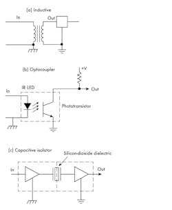
Figure 1 shows the three common isolation methods. The transformer in Fig. 1a is the most obvious—it uses two electrically isolated windings on a common magnetic core. Signals are passed by magnetic induction from primary winding to secondary winding. The isolation is excellent, but transformers have some downsides. They’re typically larger, heavier, and more expensive than other options. Though they do a good job of blocking dc, their frequency response can limit data rate unless special high-speed transformers (e.g., Ethernet) are used.
1. Common electrical isolation methods include inductive (a), optocoupler (b), and capacitive (c).
Optocoupler ICs have long been a popular isolation device (Fig. 1b). The signals to be passed are sent to an internal IR LED that switches off and on with the logic signal input to activate a phototransistor that turns off and on at the output. Isolation is excellent because of the insulated separation of the LED and photodetector.
The third option is capacitive (Fig. 1c). The signal path is via a capacitor with its insulating dielectric. A capacitive isolator readily blocks dc, but easily passes high-speed data signals and provides the ESD and transient protection indicated earlier.
Modern capacitive-isolated digital input receivers can also help simplify system design. When compared to optocouplers and other techniques, this new design approach results in advantages that include lower power dissipation, smaller boards and modules, simplified system design, and higher-speed operation.
How Capacitive Isolators Work
Figure 2 shows a simplified diagram of a capacitive isolator. The input is applied to two resistors: a sense resistor (RSENSE) that establishes the amount of current drawn from the input sensor or device, and a threshold resistor (RTHR) that sets the input logic thresholds. A comparator with hysteresis shapes the input data signal for transmission to the output across a silicon-dioxide isolation barrier.
2. Shown is a functional block diagram of a capacitive isolator such as the TI ISO1211.
Since capacitive coupling blocks dc, how do logic signals get from input to output? The answer is modulation. Capacitive isolators implement a transmitter that uses on-off keying (OOK) modulation to pass the input data through the capacitive-isolation barrier. OOK is a variant of amplitude-shift keying (ASK). A binary 1 (typically +24 V) input turns on a high-frequency carrier that’s transmitted through the capacitor barrier. A binary 0 produces no carrier. The receiver circuitry demodulates the OOK signal envelope and reproduces the data by way of an output buffer stage.
Representative of the capacitive isolators available today are Texas Instruments’ ISO1211 and ISO1212. These devices have digital input receivers that can operate over a 9- to 300-V dc (24 to 60 V typical) or ac input range with external resistors setting the current and voltage limits. They’re compliant to IEC 61131-2 specifications for Types 1, 2, and 3 inputs, and don’t require a field-side power supply. The ISO1211 is a single channel device, while the ISO1212 has two channels.
These devices can operate with a dc supply voltage in the 2.25- to 5.5-V range with low power dissipation. Input voltage protection is inherent with reverse voltage protection (±60 V). The ICs offer an excellent alternative to optocouplers for programmable logic controllers (PLCs), motor controls, and other industrial equipment. They support clock rates up to 4 MHz where typical optocouplers are limited to rates of about 20 kHz. Typical propagation delay is 140 ns compared to about 20 µs for an optocoupler.
An evaluation module for the ISO1211 is available for experimentation (SLLU258A).
Design Examples Using Capacitive Isolators
Isolation modules are used in wide range of industrial applications. PLCs, motor drives, and CNC-controlled machines in factories, process control plants, and warehouses represent several examples. This equipment gets its inputs from switches, sensors, or dc and ac voltage sources.
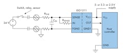
3. A 24-V or other dc source is connected to the IN and SENSE pins of the TI ISO1211.
Isolators are used to eliminate the ground-loop problems associated with long lines connecting two sources and to provide high-voltage protection. One typical arrangement is shown in Figure 3. A switch, relay, or sensor connects 24 V dc to the isolator through a threshold resistor (RTHR) and a sense resistor (RSENSE). The isolator output connects to a host microcontroller.
Some applications require monitoring remote dc or ac voltages from power supplies, battery monitors, or some relay-controlled device. To monitor ac, a bridge rectifier like that in Figure 4 is used. The ac is rectified into dc and filtered with CIN to minimize ripple to the SENSE input on the IC. Resistors limit the input voltage to the isolator. A dc source may be monitored via the capacitive isolator through a voltage divider to bring the input voltage below the upper limit of the isolator using the arrangement in Fig. 3.
4. To monitor an ac source, a bridge rectifier is used to condition the ac into a proportional dc. CIN filters out the ripple.
Capacitive-isolated comparators offer a reliable and low-power alternative to optocouplers for ±48-, 110-, and 240-V dc and ac detection. Advantages of using isolated digital inputs include precise voltage thresholds, low input current draw, higher speed, lower failures in time (FITs) higher reliability, and operation up to 125°C.
Sponsored Resources:
About the Author

Lou Frenzel
Technical Contributing Editor
Lou Frenzel is a Contributing Technology Editor for Electronic Design Magazine where he writes articles and the blog Communique and other online material on the wireless, networking, and communications sectors. Lou interviews executives and engineers, attends conferences, and researches multiple areas. Lou has been writing in some capacity for ED since 2000.
Lou has 25+ years experience in the electronics industry as an engineer and manager. He has held VP level positions with Heathkit, McGraw Hill, and has 9 years of college teaching experience. Lou holds a bachelor’s degree from the University of Houston and a master’s degree from the University of Maryland. He is author of 28 books on computer and electronic subjects and lives in Bulverde, TX with his wife Joan. His website is www.loufrenzel.com.


