A fixed-frequency signal generator that can produce outputs simultaneously at multiple phases such as 45°, 90°, 135°, and 180° is sometimes needed for testing multi-channel analog-to-digital converters (ADCs), analog filters, sample/hold circuits, and analog multiplexers.
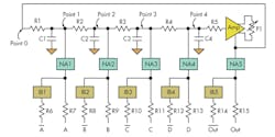
In one fixed multiphase sine-wave generator, the frequency is set by equal-value resistors R1 through R4 and capacitors C1 through C4. (Tolerance of at least ±1% is recommended.) The amplifier maintains the oscillations at stable level. Trimmer potentiometer P1 is used to adjust the oscillations for maximum stable level (Fig. 1).
The phase difference between Point 0 and Point 4 is ideally 180° because the amplifier is configured as an inverting amplifier. The difference between Point 1 and Point 4 is also 180° but divided into four equal parts, so the relative phase difference between each successive signal is 45°.
Outputs 1 through 4 should not be used directly, because any unbuffered load may affect or even halt oscillation. The buffers should also be used to adjust and equalize the signal levels. NA1, NA2, NA3, NA4, and NA5 are non-inverting buffer amplifiers. IB1, IB2, IB3, IB4, and IB5 are the corresponding inverting buffer amplifiers. The gain of each stage is set to –1 to produce the same signal levels at all inverting outputs, so the pair of outputs has the same amplitude but with a phase difference of 180°.
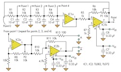
Built around IC1a and IC1b, the circuit of Figure 2 provides eight sinusoidal signals at a fixed frequency, with a phase difference of 45° between each successive output over the entire 360° cycle. It uses three quad op amps (TL084) or six dual devices (TL082) operating from ±15-V supplies (±VEE), but other op amps and supply rails can be used.
IC1a is a buffer-follower that allows high-value resistors and low-value capacitors to be used. IC1b is an inverting amplifier with gain adjusted via trimmer potentiometer P1, set for maximum stable amplitude at the generator output. With the values shown, the output frequency is about 2 kHz, but it can be set to any appropriate value with the resistors and capacitors.
The gain of non-inverting buffer IC2a is adjusted with P2 for maximum output amplitude. Each of the other non-inverting buffers has the same circuit, but the values of the gain-controlling resistors are different because the input levels from the RC network are different.
The inverting buffer is built around IC2b. It takes the signal from the output IC2a and provides the output signal with the same amplitude and the opposite phase. The other inverting buffers have the same circuit. Removing one of the RC networks (e.g., R1 and C1 from Figure 2) will change the frequency, which will then have a phase difference of 60° between two consecutive outputs.
Petre Tzvetanov Petrov is an electronics engineer with Micro-Engineering, Sofia, Bulgaria. He has worked as a researcher and assistant professor at Technical University, Sofia, and has been an expert lecturer at OFPPT, Casablanca, in the Kingdom of Morocco. He can be reached at [email protected].
About the Author
Petre Petrov
Electronics Engineer
Petre Tzvetanov Petrov is an electronics engineer with Micro-Engineering, Sofia, Bulgaria. He has worked as a researcher and assistant professor at Technical University, Sofia, and has been an expert lecturer at OFPPT, Casablanca, in the Kingdom of Morocco. He can be reached at [email protected].


