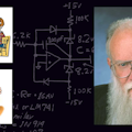
The other day, a guy wrote in requesting help. “How can I make an amplifier with adjustable positive and negative slew rates?” he asked. I instantly replied, “Easily,” and I drew this up. As soon as I got to work, I scanned and sent him the basic circuit (Fig. 1).
You turn the P1 pot until the available current through R1 is adequate to give the desired maximum negative slew rate. Likewise, turn P2 so the i through R2 is what you want for a good positive slew rate. We rarely see this circuit anywhere. If I had to find where it is in print, I probably couldn’t. Yet I made a couple in the last two years from memory. So, it is time to publish this good basic circuit.
Just choose Cf so 70 µA = i = VS/R1 = C dV/dt is as fast as you need for your fastest slew rate. Then you can slow down the slew rate by a factor of ~20 or 30:1 with the pot. For faster or slower speeds, use other values for Cf.
But if you absent-mindedly used 10k for R1 and R2, you would find that if P1 is set far differently than P2, the output would shift a lot in dc offset. That’s why 200k is better than 10k. If you went to 1M, that would work okay. Yet even if you used a FET input op amp, that might be drifty or noisy.
COOKING UP AN ADDITION That’s when I cooked up the ADDON circuit (inside dashed lines). I was going to connect point x to an inverting amplifier and feed some current to point y. This would have worked well, to compensate for any current imbalance in R1, R2, so the dc output voltage would not shift much.However, I remembered a good circuit I cooked up 40 years ago in Fort Wayne, Ind. A customer was using a photoresistor to vary an amplifier’s gain, as in Figure 2. But when the Rf went up to 5M, the amplifier became much too slow, due to the 5-pF capacitance inherent in the photoresistor. What to do?
At first I was going to use an extra op amp to make a negative capacitor to cancel out the Cf. But then I figured out it might work well if I just connected an adjustable C' back to the positive input. We tried it and it worked fine! It cancelled out the Cf under all conditions and extended the BW by 10×.
So I put in the compensation by linking point x to point z, and that worked well, too! The output offset stays within a couple dozen mV of ground, even as the pot voltages change from 1 to 14 V. Not perfect, but good.
THE RIGHT SAFETY FACTOR I’ve heard arguments that every audio amplifier should have a 7:1 or 10:1 safety factor between its actual slew rate and the biggest, fastest signal it will have to handle. I used this circuit to show that a 3:1 margin would probably not cause 0.01% distortion in that signal. I was all set to give the demo, when I discovered that nobody wanted to listen to the demo. They had made up their minds and didn’t want to listen!Anyhow, a factor of 1.5:1 or 2:1 is probably not safe, but 3 should be plenty. Don’t waste a lot of money on ultra-fast amplifiers to get a safety factor of 7 or 10. Also, don’t worry too much about slew-rate symmetry. If an amplifier is fast enough in one direction, and faster in the other direction, that’s not a big deal. I mean, who the heck spends a lot of time LISTENING TO SQUARE WAVES?! (Don’t answer that question...) (If you wanted to be sure to get matched positive and negative slew rates, you could throw out P2 and use an op amp to invert the voltage at the wiper of P1 to put the same magnitude of voltage at the foot of R2.)
As I said last year (“What’s All This ‘Best Trick Circuit’ Stuff, Anyhow?” Dec. 3, 2007, ED Online 17601), Lenny Kleinrock taught me to look at all the “breakpoints” so I would know what happens in each “piece-wise linear region” of my circuit. You’ll see some more in a short while. Hey, I just bought a couple hundred low-leakage diodes!
About the Author

Bob Pease
Bob obtained a BSEE from MIT in 1961 and was a staff scientist at National Semiconductor Corp., Santa Clara, CA, for many years. He was a well known and long time contributing editor to Electronic Design.
We also have a number of PDF eBooks by Bob that members can download from the Electronic Design Members Library.