If you have already read Jim Williams' compilation, "Analog Circuit Design: Art, Science, and Personalities," 1 then you may look on this column as a summer rerun. However, several people, after reading my 1993 comments on Frequency-to-Voltage converters, asked my opinions on Voltage-to-Frequency Converters. I realized I had written all this down already, so here is a serialized version of the chapter I wrote in Jim's book----reprinted with the kind permission of Butterworth-Heinemann, Boston, Mass. Meanwhile, I'm going hiking.----RAP
Once upon a time, there were not any Voltage-to-Frequency Converters
(VFCs) or any Voltage-Controlled Oscillators (VCOs). I couldn't tell you exactly when that was, but back in the 1950s and 1960s, very few people had ever heard about an oscillator whose frequency could be controlled by a voltage. In those days, when you wanted to change an oscillator's frequency, you usually changed a pot or a resistor or a capacitor, or maybe an inductor.
I checked up on this, because I spent a couple of hours searching in the old MIT Radiation Lab Series, published in 1949. There were no oscillators or multivibrators whose frequency could be controlled by a voltage----no VCOs, as far as you could learn by looking at the "Bible" of that time. (More comments to come on this in the next issue.)
It's true that FM radio transmitters used Frequency-Modulated oscillators, back as early as the 1930s, and these were modulated by voltages. But they only covered a relatively narrow frequency. When I refer to a VCO, I'm talking about oscillators whose frequency could be controlled over a range of 10:1 or 100:1 or 1000:1 or more. In general, this type of oscillator is expected to have a pulsed or square-wave output, not a sine wave.
Back in 1961, when I graduated from MIT and joined up with George A. Philbrick Researches (127-129 Clarendon Street, Boston 16, Mass.), I joined a company that made operational amplifiers, analog multipliers, integrators, and all sorts of Analog Computing Modules. And just about everything was made with vacuum tubes. There were Applications Notes and Applications Manuals that told you how to apply operational amplifiers (in those days we would never say, "op amp").
And there was the big old Palimpsest, a sort of collection of old stories on things you could do with operational amplifiers and analogue computing equipment. But, there were no digital voltmeters, and no voltage-to-frequency converters.
About 1963, I became aware of a high-performance operational amplifier----the 6043 project. This chopper-stabilized amplifier had been designed by Bruce Seddon, one of our senior engineers and VPs. The customer for this amplifier was Dymec, a subsidiary of Hewlett-Packard (if you turn dy upside down, does that look like hp?). And this amplifier was to be the front end of a Voltage-to-Frequency Converter instrument. The amplifiers were functioning pretty well, and they were meeting just about every specification. But they had a problem with undesired little offset shifts and jumps.
As the project went on, more and more engineers were looking over Bruce's shoulder, trying to help him solve this problem of the jumpy offset. Some people suspected that the amplifier stages might be rectifying out signals generated by ???, perhaps the transmitter of a local taxicab company? Other people suspected triboelectric effects, or electrochemical contamination.
I don't know if the cause of this drift or wobble was ever resolved----it was hard to resolve just a few dozen microvolts. But I have the impression that the amplifier project was not a success, and we never went into full production. If there was any circuitry of the actual VFC, that was never discussed at Philbrick----that was proprietary within Dymec, and our job was only to make an operational amplifier with low offset.
Of course, this amplifier had several vacuum tubes, and a chopper. The first amplifier tubes, 6CW4 nuvistors, ran with their 6-V heaters connected in series, so as to run on a 12-V dc bus and avoid the noises inherent in using 60 cps heaters. Then there were two more gain stages, dc-coupled. The chopper was an Airpax 172 or Bristol or similar, and there was a chopper amplifier based on a 12AX7. The whole circuit was similar to the Philbrick "USA-3" amplifier. It did, however, run on +/-150 V instead of +/-300 V. The late Dan McKenna, the senior technician who worked on the project, said he always suspected it was the fault of the heaters that were connected in series, because the data sheet on the 6CW4s said, "do not connect heaters in series."
But I realized later, connecting two heaters in series was surely OK; putting 10 or 20 tubes' heaters in series, as in a TV set, was the procedure that was prohibited. So, even though Dan grouched about it, this series stacking of 2 heaters was probably quite wise, not risky, because it would force the tubes to run at about the same amount of watts in each heater.
Anyhow, a design with vacuum tubes is Ancient History. Even then, although we were trying to design part of a V-to-F Converter, we didn't have a VFC in our lab. We didn't have a DVM----we had the old Fluke 805 Differential Voltmeters. Now, these meters have many elements of accuracy that good DVMs have these days, like good resolution and stability. But, they were big and heavy and slow. If you wanted to read 5.032 V, for example, you could do it, but it was a tedious deal.
You had to turn the first knob to 5, and then the next one to 0, and the next one to 3, and then turn up the Gain and look at the analog meter to see if the residue looked like a "2." That was how you learned the voltage was 5.032 V. If you've ever spent a few hours twisting the knobs of one of those old Fluke meters, you'll remember it with some nostalgia, but you must admit it was an awfully boring process.
When the first DVMs arrived from Hewlett-Packard and from Non-Linear Systems, they were slow and (in the case of the NLS) clunky and noisy, and they didn't have excellent accuracy or features compared to the old Fluke Differential Meters. But, they sure were faster and, of course, a lot easier to use.
However, there was another way to do a DVM. You could buy a Voltage-to-Frequency converter from Dymec and feed its output frequency into an "Event Counter" (an EPUT meter----Events Per Unit Time----from Beckman Berkeley). Its neon-discharge display tubes would glow and tell you what the frequency was in terms of pulses per unit of time, and that was supposed to be linearly proportional to the input voltage.
This new Dymec VFC had several solid-state circuits, and tricky pulse generators. To this day I don't know how those proprietary, secret pulse circuits were supposed to work. It had a pulse generator based on some special pulse transformers and blocking-oscillator circuits. The instrument had a pretty good tempco spec----but that's only because there was a little oven to hold all the transistorized circuits (which REALLY had a rotten tempco) at a constant temperature of +65ºC. Consequently, when you turned it on, you had to wait at least half an hour before the accuracy would finally settle out to its ultimate value; in other words, waiting for the oven to settle its temperature. It could handle a full-scale voltage of +/-1.0 V. It works pretty well. The VFC was claimed, originally, to have better than 0.02% of linearity. I measured one recently, and it had some nonlinear errors around 0.024%, which isn't bad. But, apparently, something had drifted slightly out of spec. It cost $1600, back when $1600 would buy you a Volkswagen. I still have one of the Dymec VFCs, Model DY-2211B, and the instruction book on it.
Now let's move up to about 1967. We engineers at Philbrick were working mostly on the design of solid-state operational amplifiers----amplifiers made of 6 or 8 or 10 discrete transistors and several resistors and capacitors in a compact potted module that was 1.125 in. by 1.125 in. by 0.5 in. The integrated-circuit operational amplifiers were arriving, but most of them were pretty crude in terms of performance and features.
One day, Bill Bernardi, one of the senior applications engineers, told me that a customer in Sweden had made a linear Voltage-to-Frequency Converter) using a PP85A (one of our standard operational amplifiers) and a UJT (UniJunction Transistor). And the nonlinearity was, he said, about 0.1%. When I heard this, I got kind of curious and skeptical, because everybody knows that UJTs are the crudest, dumbest, most imprecise oscillators you can find.
Just about every student learned that a UJT looks very cute because it can oscillate with a minimum amount of external parts----two resistors and one capacitor. BUT, it's an awfully junky circuit. You could gold-plate the sow's ear, and the UJT was still a junky circuit. Besides, I had recently built some Frequency-to-Voltage Converters, and it wasn't easy to get them to meet 0.1% linearity.
When I heard that a UJT was involved with a VFC of very good linearity, I was impressed, but also suspicious. So I looked into what they were doing. I didn't know anything about Voltage-toFrequency converters, but I was curious. I found that the PP85A was used as a comparator, and the UJT was mostly used to provide some "negative resistance," or positive feedback, to make a pulse whose amplitude or width aren't critical and thus didn't hurt the accuracy of the VFC. Ah, but how? How is it that a VFC which uses one simple comparator and a crude UJT pulser, and no other obvious precision components, provides a 0.1% linear VFC?
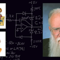
As near as I can recall and reconstruct, the circuit was basically that in Figure 1. The principle of operation is, that when the current from Vin causes the main integrating capacitor C2 to rise up to zero volts and the op amp starts to swing its output positive, the UJT is triggered. The UJT then puts out a crude pulse that kicks the minus input of the comparator. The output ALSO kicks a certain amount of charge through a charge-dispensing capacitor, C1, back to the integrating capacitor, to reset it. This amount of charge must be constant and invariant of anything, especially invariant of the repetition rate. If you can get that, you get excellent linearity. Apparently, the Swedish engineers had stumbled onto this crude but functional circuit.
Now that I understood the principles, I figured out that there was room for a good bit of improvement. I started fooling around with some breadboard circuits. I got the full-scale frequency up to 10 kHz (the Swedish circuit only worked well up to 1 kHz, which isn't nearly as useful), and got the nonlinearity down to 0.03%. And, I invented a scheme so that the operational amplifier's output could be capacitively coupled back to its + input, causing enough regeneration or positive feedback whereby the UJT was no longer needed. I used an Amelco 805BE integrated-circuit operational amplifier as the comparator.
Now, the whole circuit of Figure 2 fits into a 1.5-in. square package just 0.5-in. high----a small epoxy-potted module that was rather smaller than the PP85A amplifier and associated parts. We built up a prototype and tested it, and it worked pretty well. We potted it in our usual hard black epoxy, and shipped it to a customer in Connecticut----a customer of Larry Plante who was our Sales Engineer for that region.
Also, I sent in a Patent Application to our patent attorneys. I forget exactly who it was. Was it Curtis, Morris, and Safford in New York, or was it Schiller and Pandiscio in Waltham? No matter.
That must have been a busy year, because by the time I got off the other hot projects I had to work on for a number of high-priority customers, I realized I hadn't heard anything from this customer in Connecticut. I got in touch with Larry Plante.
All he knew was that the customer didn't like it. Worse yet, a whole year had elapsed since I had sent the part in interstate commerce, and the patent attorney had done nothing, so the patent application was now worthless.
I was quite cross, and I read the Riot Act at those attorneys. Then I set in at the workbench with a vengeance. And that led to the 4701 Voltage-to-Frequency Converter, which I'll tell you about in the next issue's Pease Porridge column.
All for now. / Comments invited! RAP / Robert A. Pease / Engineer
Address:
Mail Stop D2597A
National Semiconductor
P.O. Box 58090
Santa Clara, CA 95052-8090
References:
1. "Analog Circuit Design: Art, Science, and Personalities," edited by Jim Williams, 1991. 398 pages. Butterworth-Heinemann, Boston, Mass., (800) 366-2665. About $51. An excellent book; you should have your librarian order it.
About the Author
Bob Pease
Bob obtained a BSEE from MIT in 1961 and was a staff scientist at National Semiconductor Corp., Santa Clara, CA, for many years. He was a well known and long time contributing editor to Electronic Design.
We also have a number of PDF eBooks by Bob that members can download from the Electronic Design Members Library.
Voice Your Opinion!
To join the conversation, and become an exclusive member of Electronic Design, create an account today!

Leaders relevant to this article: