While working engineers were designing hardware for production, a large controversy erupted regarding the validity of Kirchhoff’s law. The controversy sprang up when Mehdi Sadadhgar posted this YouTube video challenging former MIT professor Walter Lewin:
Sadadhgar is not a crank—he has over 2.5 million subscribers for his electrical engineering videos. The video he posted has 650,000 views. He has a Master’s in electrical engineering and observes, “My mom thinks I am mostly OK.” In the video Sadadhgar politely and respectfully observes that Lewin teaches in an online course that “Kirchhoff’s voltage law, or KVL, doesn’t hold true in some cases...” Sadadhgar suggests that Lewin may have a problem with the probing of the circuit.
Walter Lewin’s “Paradox”
Lewin is a physicist, and maintains that it is Faraday’s law, not Kirchhoff’s, that always holds true. Sadadhgar cites four of Lewin’s videos. The first, "8.02x- Lect 16 - Electromagnetic Induction, Faraday's Law, Lenz Law, SUPER DEMO," has 1.2 million views and gives an overview of Faraday’s observations on induction between a solenoid and a loop of wire enclosing the solenoid:
It’s based on a 2002 paper Lewin wrote. To Lewin’s credit, he does a physical demonstration of a solenoid inducing a current in a loop of wire.
The video that likely incited Sadadhgar’s disagreement has the combative title "Kirchhoff's Loop Rule Is For The Birds":
Lewin states he will be teaching “...something so non-intuitive that almost all college physics books have it wrong.”
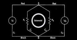
Lewin starts the lecture with a simple circuit diagram with two resistors in a loop with a nearby solenoid (Fig. 1). Most electrical engineers will realize that either energizing or turning off the solenoid will induce a current in the loop, with the commensurate voltages being created across the resistors. Lewin goes on to show two voltmeters on each side of his two-resistor circuit (Fig. 2). He does the math to show the voltmeters will read differently, despite being hooked to the same two points.
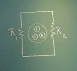
1. Walter Lewin sets up his “paradox” with two resistors in a loop that has a nearby solenoid. The circles with dots in the center are looking down on the arrowheads representing the magnetic field coming out of the blackboard. (Courtesy of YouTube)
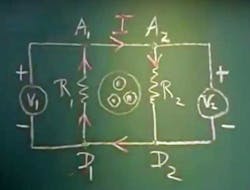
2. Lewin goes on to show two voltmeters attached to the loop, and fills the blackboard with math that shows the voltmeters will read differently due to path dependency. (Courtesy of YouTube)
In Lewin’s video, he refers to one of his earlier lectures where he hooks two oscilloscopes in place of the voltmeters (see "SUPER DEMO" video above). Sure enough, despite being connected across the same circuit nodes, the oscilloscopes produce different readings (Fig. 3). Lewin credits Faraday, but most engineers would recognize there’s a clear probing problem, since the probe wires also form loops that have voltages induced by the changing magnetic field of the nearby solenoid.
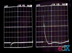
3. Lewin then connects two oscilloscopes in place of the voltmeters and applies a step function to the solenoid. The ‘scopes read differently, in agreement with Lewin’s math. (Courtesy of YouTube)
A Lesson in Good Probing
The probing issue was clearly demonstrated in a video by Cyriel Mabilde of Ghent University in Belgium. He posted a video, “Walter Lewin: electromagnetic induction=not for the birds (lecture 16)” that has some truly great experimental results:
Mabilde notes how Lewin says the EMF (electromotive force) must be in the resistors, since as long as the voltmeter or oscilloscope in on the same side, moving the probe points closer or further from either resistor yields the same value. Mabilde then notes Lewin’s contradictory observation that the EMF must exist in every part of the wires. He admits Lewin’s demonstration was “against all intuition.” He then states, “I will try to dispel the doubts, not by proclaiming a new theory, but by repeating the experiment in a clearer way.”
Mabilde then builds a precise solenoid and fashions a two-resistor circuit with copper foil instead of a wire (Fig. 4). He uses a near-field probe to map the magnetic field surrounding the solenoid when he excites it with an ac current. He fashions a loop to demonstrate the zero-flux plane (Fig. 5). He then uses a probe tip with a brush to connect at any point in the copper foil that connects the two resistors. Mabilde then clearly shows the scope result depends on which side of the circuit that you hang the probe wires. He notes, “The measurement error in the wiring as the same order of magnitude as the value we want to measure.”
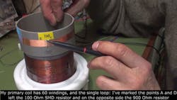
4. Cyriel Mabilde built a setup to demonstrate the probing issues in Lewin’s setup. He made the single loop with two resistors using copper foil, so he can probe anywhere along the “wire.” (Courtesy of YouTube)
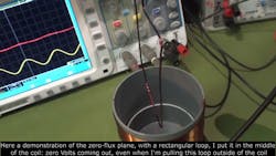
5. Cyriel Mabilde improves Lewin’s demo by exciting the solenoid with ac current instead of a momentary pulse. He shows how a coil of wire in the mid-plane of the solenoid is in a zero-flux environment. (Courtesy of YouTube)
Next, Mabilde goes on to use a 5-turn loop in the circuit with the two resistors, to show how the measurement error is proportionally smaller. He then builds an internal loop with the probe wires leaving in the zero-flux plane (Fig. 6). He demonstrates you can measure the EMF in the loop wires if you make sure the probe wires are not adding or subtracting to the measurement. Mabilde concludes, “...the single loop is a very special transformer: if you want to investigate it, be careful to avoid extra unwanted measurements. We know that Kirchhoff is right in this case…. Invoking the theory of path dependency in not the right answer for explaining these simple measurements.”
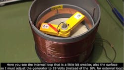
6. Mabilde then makes a two-resistor loop that fits inside the solenoid, so he can get the probe wires routed out along the zero-flux plane. Afterward, he shows that EMF exists along the wires, in accordance with a paper by Princeton’s Kirk McDonald. (Courtesy of YouTube)
Conflict Sells
It’s interesting to note that both Sadadhgar and Lewin have millions of views, while Mabilde has 4,360. His video shows the majesty of the scientific method and the precision and diligence needed to set up good experiments. People must find that boring. This explains why Clint Eastwood insists on conflict in his movie scripts. If you watch just one video in this whole article, make it Mabilde’s.
Mabilde based his video on a paper written by Kirk T. McDonald of Princeton University (Fig. 7). Titled “Lewin’s Circuit Paradox,” McDonald notes, “Kirchhoff never applied his laws to time-dependent circuits, such as in Lewin’s example.” So, what we have is a classic case of “it’s all in the definitions.” If you define Kirchhoff’s law as what Gustav Kirchhoff stated in 1845, well, Lewin is right, the law doesn’t hold for Lewin’s circuit example. Yet electrical engineers think of Kirchhoff’s law as the refined principle that incorporated time-dependent circuits and energy addition. McDonald explains how Kirchhoff’s law was improved by Heaviside, Helmholtz, Thomson, and Maxwell himself.
7. Professor Kirk McDonald of Princeton University at the Temple of Heracles. (Courtesy of Kirk McDonald)
Kirchhoff and Spice
I wonder how Bob Pease would have reacted to this brouhaha. We know he hated Spice, and said “Spice lies!” Spice uses matrix math to solve Kirchhoff’s equations, so if Kirchhoff is wrong, then so is Spice. Most electrical engineers would look at Lewin’s circuit and see that he has a model problem. His circuit shows simple wires connecting the two resistors when, in reality, they are the secondary coil of a transformer. If you change the circuit to show the coils, Kirchhoff’s law works once again. You can similarly account for thermal losses or energy gains, you just have to model it in the schematic.
Things get murkier with transmission lines, but Spice can solve for that, too, within limits. At RF frequencies, the potential in a wire changes along its length. Also, every component in your circuit is radiating and receiving energy from the other components and the outside world. That’s when Kirchhoff and Spice no longer apply.
The joust between Sadadhgar and Lewin got quite heated. Lewin did two follow-on videos. One is titled "ha ha ha 5 + 3 - 8 = 0," where he restates his contention that Kirchoff does not always work:
He responds to his critics by claiming they are using circular reasoning, as in the arithmetic in the title. In his next video, "Believing and Science are Very Different," he addresses what he feels are criticisms to his argument. Lewin comes across as dismissive, haughty, and arrogant in these videos, which does not help his case:
Then Lewin directly addressed Sadadhgar’s video with "To Agree or Not to Agree that is Not the Question," and "To Agree or Not to Agree with the Master that is Not what Matters":
Lewin’s Apology
At the end of the video, Lewin ridicules Sadadhgar, without naming him, for Sadadhgar’s contention that Lewin has a probing problem. Big mistake. Three days later, Lewin posted the video "My Sincere Apologies::
He once again invokes Romer’s paper, still maintains that he is right, and says that a “modern” interpretation of Kirchhoff’s law that deals with non-conservative external fields is “a joke.” Lewin says “If I was too blunt and not very tactful, I sincerely apologize. Yes, I really mean that.” He then encourages Sadadhgar to keep “entertaining his followers.”
I am sure this apology came about because of the thousands of Sadadhgar viewers who bombarded Lewin with hostile and often profane comments. Thirteen days later, Sadadhgar ended the confrontation with his video, "Kirchhoff's Voltage Law versus Faraday's Law: the Conclusion":
Sadadhgar posts a paper by John W. Belcher, an MIT physics professor (Fig. 8). The paper gives a very rigorous examination of why the two oscilloscopes in Lewin’s demonstration gave different readings when attached to the same points in the circuit. To me, it sure seems like the “probing error” that Lewin ridiculed Sadadhgar for suggesting. The video description also cited a lecture by physicist Richard Feynman about Kirchhoff’s law. I see this as the “modern” interpretation of Kirchhoff’s law that Lewin ridiculed.
8. MIT professor John W. Belcher wrote a paper specifically addressing the Lewin “paradox,” and the observations of Mehdi Sadadhgar, known as ElectroBoom on YouTube, in his popular EE videos. (Courtesy of MIT)
The Sociology of Technical People
I find this entire argument more a lesson in sociology than physics. Where Lewin comes across as haughty and self-absorbed, Sadadhgar is engaging and clowns around, purposely shocking himself and creating explosions. It does not help Lewin’s case that he was stripped of his emeritus professorship by MIT after they discovered he was sexually harassing female students in his online course. I link to it in case you think it was a silly thoughtless comment or suggestive glance. No, it was some really despicable behavior. This should have no effect on our judgment of the science, but as they say on Perry Mason, “It goes to the witness's character, your Honor.”
From the comments in the videos, you can see lines drawn between physicists, who tend to support Lewin, and engineers, who take the side of Sadadhgar. Like it or not, we are tribal animals. Now, the Wikipedia entry on KVL notes its limitations. It states, “KCL [Kirchhoff’s current law] and KVL both depend on the lumped element model being applicable to the circuit in question. When the model is not applicable, the laws do not apply. KCL and KVL result from the assumptions of the lumped element model.” So, you can see Lewin’s point. If the wires connecting the two resistors are modeled as superconducting nodes like he states, and you ignore that they are part of a single-turn transformer, yeah, Kirchhoff does not work.
Sadadhgar is certainly right that two points in the circuit can’t be at different potentials just because the voltmeter is on different sides of the circuit. It is a probing problem. The thing that Lewin ignores is that voltmeters do not measure EMF at the probe tips. They measure the voltage created across their source impedance caused by a current flowing in the probe wires. We have all seen cell phones and air-conditioning units cause errors in our ‘scope probes. I would like to observe Lewin’s circuit in an electron microscope where you can observe the wire potentials directly, without probes, using voltage contrast microscopy:
So, the stubbornness and arguments are because everyone has a slightly different idea of what Kirchhoff’s law really is. Many of us would model in the solenoid's effect with a transformer element in the circuit. That would give the right result, but it’s not quite the letter of Kirchhoff’s law.
Commenter RedTriangle53 noted, “If you propose that Kirchhoff's law holds under a varying magnetic field you're basically disagreeing with one of Maxwell's equations (Faraday's law). Under a varying magnetic field, the E-field has curl and so is no longer conservative, and the core assumption of Kirchhoff's law stops being valid (that all closed path integrals over E are zero). I'm amazed at how many self-proclaimed PhDs in electrical engineering in the comment section are confused about this. Could be due to a difference in how physicists are taught electromagnetism vs. electrical engineers. Maybe if you separate the E-field into a conservative part and a non-conservative part and only allow the conservative part to have "voltage", maybe it makes sense, but this seems incredibly contrived to me. It would be interesting to hear if electrical engineers learn things differently, and in that case how.”
Thing is, we all use Spice, especially LTSpice, to solve power-supply circuits with varying magnetic fields. All of us accept Faraday’s Law. Another commenter, woowooNeedsFaith, states, “Modern ‘modified KVL’ is Faraday's law in disguise. If you have seen Lewin's videos you should have heard it in one form or another... Start with this [see the "ha ha ha 5 + 3 - 8 = 0 video above]. Then here are the derivations in the wrong way [top video] and the right way [bottom video]:
So, I do see the physicists’ point. Just like Spice runs out of steam in an RF circuit, KVL might not be the right tool to solve a problem with those non-conservative fields that get people so worked up. The thing is, engineers are not concerned with purity or fidelity to laws. We are trying to get working hardware out the door. If we can “fool” Kirchhoff’s law to get the job done, we are not cheating—we are getting the problem solved with arithmetic instead of calculus. Laplace transforms do the same thing, and let’s all be thankful for that.

About the Author

Paul Rako
Creative Director
Paul Rako is a creative director for Rako Studios. After attending GMI (now Kettering University) and the University of Michigan, he worked as an auto engineer in Detroit. He moved to Silicon Valley to start an engineering consulting company. After his share of startups and contract work, he became an apps engineer at National Semiconductor and a marketing maven at Analog Devices and Atmel. He also had a five-year stint at EDN magazine on the analog beat. His interests include politics, philosophy, motorcycles, and making music and videos. He has six Harley Sportsters, a studio full of musical instruments, a complete laboratory, and a video set at Tranquility Base, his home office in Sun City Center Florida.
Comment About the Article
To join the conversation, and become an exclusive member of Electronic Design, create an account today!

Leaders relevant to this article: