Move Beyond Active Filter Design Mythology To Improve Your Discrete Op-Amp-Based Designs
Almost all efforts immediately constrain implementations by unity gain in the op amp, equal R or equal C, or both. When multi-stage filters are implemented with gain, most of the gain is placed in the earliest stages. These assumptions don’t always lead to particularly good results. But they are entrenched in the literature and most online design tools as a sort of design mythology.
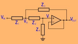
How do these “myths” arise? For a single second-order stage, the designer is really only after three performance elements: dc gain, ω0 (the characteristic frequency of a second-order pole pair), and Q (an indication of the complexness of the poles). However, the circuit gives you five elements to resolve: the two R’s, the two C’s, and the amplifier gain.
Constraining your design flow to just unity gain and equal C (a very typical approach in academia) removes two of those pesky degrees of freedom, leaving you a unique set of R’s that will hit the ω0 and Q once you have chosen some desirable equal C values.
Many authors also deem equal C desirable to get better matching in the C’s, particularly when the effort is headed toward IC implementations. Also, in the earliest days, it was no small task to come up with amplifiers fast enough to implement these filters reliably without considerable production variation, and unity gain certainly helps with that issue.
The last 25 years have brought major advances in op amps and passives. Low-power/low-cost voltage feedback (VFA) op amps with unity gain stability and bandwidths in excess of 1 GHz are available. Also useful are current feedback op amps (CFA) that hold relatively constant bandwidth over gain, so they are very uesful in SKF stages that require gain. These are available at low power and low cost with bandwidths exceeding 500 MHz over gains from 1 to 10.
Some sources imply the CFA topology cannot be used in an active filter circuit. Much like the ancient fear that viewing the Medusa would turn you into stone, this myth spreads unnecessary trepidation where in fact these devices are very useful in SKF low pass stages. Finally, C0G dielectric, 1% multilayer ceramic capacitors (MLCCs) with low temperature drift are also available at low cost.
From Myth To Reality
With these improvements in the SKF building blocks, it seems time to move beyond these legacy constraints and deliver better solutions. Since the absolute accuracy of the R’s and C’s have improved, and amplifier bandwidths over a wide range of gains is far better today, it’s time to leave behind these myths of low or unity gain, equal C, or equal R and focus instead on more interesting issues inside the SKF.
Given the under-constrained nature of the SKF, it is still important to realize that an infinite range of R and C combinations will give you the same target ω0 and Q (if you have a particular gain in mind at low frequencies setting the amplifier gain). The next most interesting thing is to bias the R and C selections to improve the dynamic range in the passband.
This suggests that the noise added by the two filter resistors should not add significantly to the noise produced by the op amp and that the “noise gain” inside the SKF should not peak more than it already does due to the target filter poles. These two ideas lead to lower noise and distortion solutions and show up physically with R’s that are relatively low and in a ratio of 0.15 to 0.7 (where this is the ratio of the input resistor to the second resistor feeding the op-amp input).2
Constraining the resistor sum to reduce their noise impact and their ratio to reduce noise gain peaking leaves only the two C’s to be resolved to hit the desired filter shape. This target resistor ratio also moves in the direction of better sensitivity and gain margin as reported by more recent authors.3
This same issue of noise gain peaking inside the SKF loop gain also leads to a different gain sequencing in multi-stage filters than typically reported. It is quite common to see most of the gain in the first stage. This is the right thing to do if low-frequency spot noise were the dominant contributor to total output integrated noise.
The noise gain peaking hiding inside the SKF can outweigh this issue and suggests the highest Q stage first at a low amplifier gain for a multi-stage filter. This physically provides a large noise peak at the output of that first stage. Note that asking for a lot of dc gain in this stage is going in the wrong direction. The subsequent lower-Q, higher-gain stages then will “filter” this noise peak. Comparative simulations of output spot and integrated noise have validated this approach.4
While there has been a vast amount written on the SKF, most of it seems to have been produced for IC implementation (low and matched C values) and/or well before the easy availability of wideband op amps and low-cost precision surface-mount device (SMD) capacitors. Take advantage of the fabulous SKF design elements that are available today, and move beyond the myths to improved dynamic range designs.
References
1. Sallen, R.P., Key, E.L., (1955-03), “A Practical Method of Designing RC Active Filters,” IRE Transactions on Circuit Theory
2 (1), 74-85 2. Intersil/Renesas iSim Active Filter Designer, www.intersil.com/iSim
3. “A new set of Sallen-Key filter equations,” Martin Cano, EDN, Oct. 1, 2009
4. Intersil Application Note AN1580, “Testing Intersil’s ‘Active Filter Designer’ gain and Q Sequencing Impact on Output Noise,” Michael Steffes and Oscar Mansilla, July 2010.
About the Author

Michael Steffes
Analog Signal Path Consultant
Starting as an IC design engineer at the original current feedback amplifier company (Comlinear), I progressed through 35 years of high speed amplifier development projects. Through these years I contributed to the definition, development, and product launch (datasheets and simulation models) of over 150 high speed amplifiers. Generating the related technical collateral also produced over 150 contributed articles and application notes..
Comment About the Article
To join the conversation, and become an exclusive member of Electronic Design, create an account today!

Leaders relevant to this article: