Back about 1965, when I was at Philbrick, we were doing some business with Amelco Semiconductor. I had designed a good hybrid op amp (the Q85AH) and Amelco was trying to build it, but they had some test problems, and some yield problems... so I flew out to help find and solve their problems.
The first morning, I put in an hour looking at their test setup. Nothing showed up right away. So we went over to their cafeteria for a cup of coffee. Several engineers were there, talking about circuits. Hey, amplifier circuits! Op-amp circuits!! So I quietly looked over their shoulders and prepared to join in. But shortly I realized they were studying a different op amp—not mine. I became politely annoyed.
“Hey, guys, I flew all the way out here to solve your amplifier problems. Why are you working on this other junk?” They said their corporate leaders had “volunteered” them to design a little seismic amplifier for NASA, for “lunar earthquakes,” and they were having some problems making a good amp design.
“Tell me about this requirement,” I said. “Maybe I can help.” I was trying to get them back to work on my amplifier and its problems. So they showed me the requirements. I don’t recall how they were written, nor for what specs, but the input had to have high ZIN—a FET—and have low noise, and behave well with a gain of 100 or more, and draw low power.
BACK OF THE ENVELOPE SOLUTION
I scribbled some notes as I looked over their problem. It took me about 12 minutes, using gm = 40 i and such simplified rules. So I stood up and told them, “You get a technician to grab these necessary parts, and I’ll design the circuit for you in half an hour. The technician can build it up this afternoon... And now you can go back to work on my amplifiers... You can evaluate your amplifier circuit tomorrow morning.”
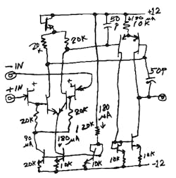
I started scribbling a circuit, and they looked at it, and the list of parts, and thought about it, and sent a technician for parts. They agreed it was quite likely to work okay (see figure). It was (for its day) a very classical, simple little amplifier.

The 120k resistor was the biggest R we could get in the little hybrid package, the largest we could beg, steal, or borrow. I got the gain up over 50,000 when driving RL = 100k. And I beat the power drain goal of 50 mW by a factor of better than 2. Good enough is good enough.
To get the gain good and high, we needed a beta of 300 min on the input NPNs (2N930-type) and beta of 200 on the PNPs (2N2605’s). I could have gotten a bit higher performance if I had put in more parts, but that would likely have increased the problem of “We want it to work right the first time, with no trouble.” That was a reasonable goal.
I put in some good bias circuits to help make sure it was well-behaved, well beyond the MIL temperature range. Without any serious studies, we knew the temperature on the moon would go well beyond that. I suspect it worked well over 195°C to –95°C, but I never tested it versus temperature.
The first one played as it was designed. Those engineers went off and made up a couple dozen for NASA. They also made up some to sell from their catalog— the 2401BG. I don’t think they ever sold very many, and it was not easy to apply, as it was optimized for a gain above 50 and wanted to oscillate for gains below 20. But, hey, it was optimized for a gain of 100.
UP ON THE MOON
A few of these little fellows were put into “Lunar Seismic Probes” and evaluated fully. When Apollo 12 landed on the moon on Nov. 20, 1969, one set was left behind, parked a few dozen yards from the Lunar Lander, all wrapped in gold foil. It sent back all sorts of noises from various noisy seismic events. So when anybody shows me a photo or mockup of the lunar landing site, I just point over to the corner and say, “Yeah, that’s my junk, over there.”
Comments invited! [email protected] —or: Mail Stop D2597A, National Semiconductor P.O. Box 58090, Santa Clara, CA 95052-8090
About the Author

Bob Pease
Bob obtained a BSEE from MIT in 1961 and was a staff scientist at National Semiconductor Corp., Santa Clara, CA, for many years. He was a well known and long time contributing editor to Electronic Design.
We also have a number of PDF eBooks by Bob that members can download from the Electronic Design Members Library.
Comment About the Article
To join the conversation, and become an exclusive member of Electronic Design, create an account today!

Leaders relevant to this article: