Changing LED into Gold: SEPIC Converters Tame Automotive Battery Fluctuations

Download this article in PDF format.
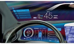
Use of electronic displays continues to expand in automotive applications (Fig. 1). Behind the wheel, they’re replacing individual electromechanical instruments as well as complete instrument clusters. In infotainment, applications include radios, navigation displays, and headrest displays for rear passengers.
Augmented reality (AR) is another application. A head-up display superimposes an image on the windshield to give the driver key information while they’re concentrating on the road ahead.
Sponsored Resources:
- PCB Layout Guideline for Automotive LED Drivers
- SEPIC Mode Converters for Automotive LCD Displays - Technical Overview
- Light Up Your Design with TI's Best-in-Class LP8863-Q1 LED Backlight Driver
1. The automotive dashboard of the future will combine LCD and HUD technologies. (Source: TI Blog: “The sleigh of the future with DLP technology”)
Automotive displays such as these predominantly use liquid-crystal-display (LCD) technology. The illumination source is provided by multiple light-emitting diodes (LEDs) placed around the edge of the flat-panel display screen. This arrangement is known as an LED-backlit LCD.
The number of LEDs depends on application parameters such as the required brightness, the width of the display, and its resolution. The trend is toward displaying more information with larger, higher-resolution units. A 12-in. display with FHD (1920 × 1080) resolution, for example, might require up to 40 LEDs for a brightness of 1000 nits (candelas per square meter).
The LCD panel manufacturer determines the LED configuration. A single string of many LEDs in series is one option, but a more usual configuration is several shorter series strings arranged in parallel.
LED Driver Fundamentals
The goal of the LED backlight driver is to keep the LED brightness at the desired value independent of changes in temperature, supply voltage, or other variables. The brightness of an LED is proportional to its forward current when the device is biased with a forward voltage (VF). VF varies with color: for backlight white LEDs, VF ≈ 3.0 V at 80 mA @25°C. The forward voltage is also temperature-dependent—1 mV/°C is typical—and process variations can add another 200 mV.
Over a −40 to 125°C operating range, an 8-in. LCD with 15 LEDs arranged in three strings of five therefore requires an LED supply voltage of between 14.175 and 16 V.
The simplest LED driver circuit consists of a power source, the LED string, and a series resistor to limit the current. However, more sophisticated backlight drivers typically regulate the current with a constant-current sink and add the capability to control the brightness.
Many LED backlight drivers in non-automotive applications can rely on a stable power supply. For example, notepads and cellphones use one or more 3.7-V Li-Ion battery cells, and an industrial application might have a system power supply of 36 V or 48 V. Check out Texas Instruments’ portfolio of LED drivers for more information.
In an automotive application, though, the power source originates with the vehicle battery, not exactly a stable, well-regulated power source. The voltage on the battery line (VBATT) is nominally 12 V, but this can vary widely during the operational life of the vehicle. There are several reasons for this variation, such as normal battery charging, transient events, faults, and mistakes.
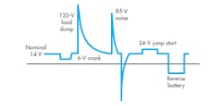
2. The voltage on the battery line can vary from 6 to 24 V during normal operation, and from 120 to −85 V during transient or abnormal conditions. (Source: TI Training: “SEPIC Mode Converters for Automotive LCD Displays”)
Figure 2 shows some of the disturbances and their effects on VBATT. The key events are:
- Normal operation with engine running: The voltage on the VBATT line is approximately 14 V while the engine is running and the alternator is continuously charging the battery. This can increase to 16 V or 18 V when the RPM surges during a throttle tip-in.
- Cold crank: Cranking the engine during cold temperatures requires the maximum current draw from the battery. The voltage can sag to as low as 3 V for a short time (around 15 ms), although 6 V is a more common specification limit.
- Load dump: This abnormal condition occurs when the battery (load) becomes disconnected while the alternator is delivering current. When this happens, the inductance of the alternator windings causes a large voltage spike on VBATT that takes up to 400 ms to decay. This voltage can be as high as 120 V, but modern centrally suppressed alternators include circuits that limit this to around 40 V.
- Jump start: The system must survive a 24-V jump start using two 12-V batteries connected in series. Using a 24-V system is especially likely in cold weather.
- Electrical transients: Since so many pieces of equipment draw their power from the VBATT line, it’s subjected to various switching transients up to ±85 V.
- Reverse battery: The vehicle’s electrical system must survive a sustained negative voltage due to the battery being inadvertently connected backwards.
The LED backlight driver must be able to withstand these conditions. The automotive industry uses the pulses in the ISO7637 standard to test the response of electronic modules to VBATT disturbances. Read more about LED driver protection techniques in this application report.
Going SEPIC in Automotive LED Backlight Driver Design
There are many switched-mode techniques to choose from when converting one voltage to another. The table shows some of the standard non-isolated switching power-supply topologies. Which one is best for an LED driver?
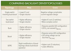
(Source: TI Training: “SEPIC Mode Converters for Automotive LCD Displays—Technical Overview”)
In industrial or consumer applications, LED backlight drivers can safely use buck or boost topologies because the system voltage is reliably above or below the LED string voltage. That’s not the case with VBATT, so a buck-boost converter is the preferred topology for automotive applications.
The simplest buck-boost topology gives an inverted output. This could be used to drive the low side of the LED string, but the negative voltage complicates the current sink’s design. The two-switch buck-boost is an efficient option, but costs more and requires a more complex control scheme.
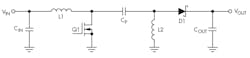
3. The basic SEPIC topology is a simple modification of the boost topology of a buck-boost converter. (Source: TI Training: “SEPIC Mode Converters for Automotive LCD Displays” video)
The single-ended primary-inductor converter (SEPIC) is a non-inverting buck-boost converter that’s a simple modification of the standard boost topology (Fig. 3). The SEPIC isn’t as efficient as other topologies, although it has only two active components: the switching transistor and the output rectifier. The extra inductor does increase the cost.
The SEPIC has a smooth transition between buck and boost modes as VIN changes, so there’s no flickering of the display. Coupled with its non-inverting output, the SEPIC is the preferred choice for automotive LED driver applications. Moreover, it maintains a continuous input current, which means it has a low input ripple voltage, thus minimizing input capacitance and reducing electromagnetic interference (EMI).
SEPIC Operation
Figure 4 shows the idealized waveforms of the SEPIC. The average inductor current of L1 equals the input current (IIN), and the average inductor current of L2 equals the output current (IOUT).
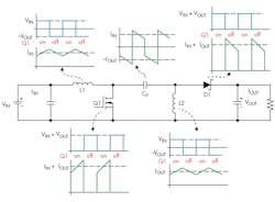
4. Shown are ideal waveforms of the SEPIC. (Source: TI: “Design tips for an efficient non-inverting buck-boost converter” PDF)
When the FET Q1 is on, the input current (IIN) flows to ground. The same is true for the output current (IOUT), through the input-output coupling capacitor (CP). Current IIN + IOUT flows through the FET and the output rectifier D1 is reverse-biased.
When the FET is off, D1 is forward-biased and the input current IIN flows directly to the output through D1 and CP. IOUT now flows directly into the output—the current through D1 is IIN + IOUT, which is the same as the FET current in the on state. The direction of the current in CP is now reversed and flows from left to right, with an amplitude of IIN.
There are two switching voltages: one on the FET, and one on the anode of D1. The FET voltage is equal to zero when the FET is on.
When the FET turns off, the VDS voltage flies up to a voltage equal to the output voltage plus the voltage across CP, i.e., VIN + VOUT. The voltage on the D1 anode is VOUT: the voltage on the FET, less the dc voltage of the coupling cap, VIN. When the FET is turned on, the anode voltage goes negative to −VIN.
D1 must be able to handle both the peak value of IOUT and the peak reverse voltage. A Schottky diode with its lower forward-voltage drop and fast switching is required to reduce losses and increase converter efficiency. It’s preferable to use ceramic capacitors with low equivalent series resistance (ESR). These reduce power loss but increase cost.
The ratio of VOUT to VIN is:
VOUT/VIN = D/(1 – D)
where D is the duty cycle. The SEPIC acts as a buck converter when D < 50%, and as a boost converter when D > 50%.
The two inductors L1 and L2 can be wound on the same core to form a coupled inductor, since the same voltages are applied to them throughout the switching cycle. A coupled inductor takes up less PCB space and is usually cheaper than two separate devices; on the downside, there’s usually a limited selection of off-the-shelf components.
See this application report for a more detailed SEPIC design discussion. This article from TI’s Analog Applications Journal discusses design tips to improve SEPIC efficiency.
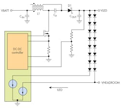
5. A coupled-inductor SEPIC-based LED driver can power multiple LED strings, each with a current sink to regulate ILED. (Source: Author and TI “SEPIC Mode Converters for Automotive LCD Displays” training video with Jeremy Yaeger)
Figure 5 shows a SEPIC driving two parallel LED strings. It consists of the circuitry discussed earlier, plus a controller integrated circuit (IC) and a current sink for each string. VBATT is the input to the SEPIC; the output voltage VLED is a common power source for the LEDs. A resistor divider provides scaled voltage feedback to the controller.
VHEADROOM is the voltage on the low side of the LEDs that the current sink needs to regulate the LED current (ILED). For the LP8863-Q1 LED driver, discussed later on, the typical value is 0.55 V.
How do changes in VBATT affect the operation of the circuit? Figure 6 shows the effects of VBATT variations on the voltage and current seen by the LEDs.
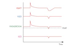
6. Key voltages in the life of an LED string. (Source: TI Training: “SEPIC Mode Converters for Automotive LCD Displays” with Jeremy Yaeger)
A positive transient causes VBATT to rise, causing a rise in both VLED and VHEADROOM. The LED current does not rise: It will remain regulated so long as the HEADROOM voltage is above the minimum saturation voltage (VSAT).
A transient that’s too short for the controller to respond will pull the converter output, VLED, high and increase the current through the LEDs. The transient will increase the thermal stress, but not enough to pose a reliability issue.
A load dump, though, might last for hundreds of milliseconds. That’s long enough for the SEPIC to switch from boost to buck operation.
During a cold crank, VBATT drops, causing VLED to drop. If the HEADROOM voltage falls below the saturation voltage, the LED current will drop, causing blinking or flashing of the display. The SEPIC driver switches to boost mode to keep VLED at an acceptable level.
Controlling LED Strings with the LP8863
TI has a portfolio of SEPIC devices optimized for automotive backlight applications with different feature sets. All devices are qualified to the AEC-Q100 standard.
The LP8863-Q1, for example, is a high-voltage multichannel backlight LED driver with independent duty cycle and current control for each channel. The six LED current sinks provide up to 150 mA per channel and can be tied together to support higher current LEDs. The device is able to operate in either boost or SEPIC modes. Figure 7 shows the SEPIC configuration.
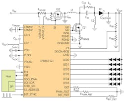
7. The LP8863-Q1, shown in SEPIC configuration, can control up to six independent LED strings. The part can use either coupled or uncoupled inductors. (Source: LP8863-Q1 PDF)
The LP8863-Q1 sets VOUT using an adaptive control scheme based on the headroom voltages of the LED current sinks. This method adjusts VOUT to the minimum value needed to drive the LED strings in all conditions, minimizing power consumption.
In boost mode, a resistor divider connected from VOUT to the FB pin sets the maximum voltage. During SEPIC operation, the switching FET sees a voltage of (VIN + VOUT); therefore, the LP8863-Q1 limits VOUT to 24 V.
LED dimming: The LP8863-Q1 leverages two methods to dim the LEDs. PWM dimming, the default setting, dims the LED strings globally by reducing the PWM duty cycle. The hybrid dimming setting combines PWM dimming and current dimming, which reduces the current for each channel individually via I2C or SPI.
PWM dimming gives accurate linear control at low brightness levels. Current dimming at high brightness levels increases the total optical efficiency, reduces EMI, and extends the LED lifetime.
Cluster mode: The LP8863-Q1 also includes a cluster mode that supports up to six individually controlled channels or, alternatively, three to five channels for a display and three to one individual channels for indicator lights. In this mode, all strings can be connected to the LP8863-Q1 VOUT, or an external supply can be used for indicator channels.
Resistor RBST sets the switching frequency of the LP8863-Q1 to between 300 kHz and 2.2 MHz. The wide adjustment range helps the LP8863-Q1 minimize AM radio-band interference. An external frequency signal can also be used to synchronize multiple devices.
A comprehensive set of collateral is available, including an evaluation board, an external component selection guide, and a graphical user interface (GUI). A set of detailed training videos covers SEPIC operation and design.
Conclusion
Although LCD displays are increasing their penetration into automotive applications, the large variation in the battery supply voltage poses challenges for the LED backlight driver design.
Texas Instruments has developed a portfolio of backlight drivers for automotive displays that uses the SEPIC topology coupled with specialized features to simplify the task, including comprehensive design support.
Sponsored Resources:
About the Author
Paul Pickering
Paul Pickering has over 35 years of engineering and marketing experience, including stints in automotive electronics, precision analog, power semiconductors, flight simulation and robotics. Originally from the North-East of England, he has lived and worked in Europe, the US, and Japan. He has a B.Sc. (Hons) in Physics & Electronics from Royal Holloway College, University of London, and has done graduate work at Tulsa University. In his spare time, he plays and teaches the guitar in the Phoenix, Ariz. area
Comment About the Article
To join the conversation, and become an exclusive member of Electronic Design, create an account today!

Leaders relevant to this article: