EV Success Hinges on Smarter, Faster Charging Stations
Download this article in PDF format.
Zero emissions vehicles (ZEVs), including electric vehicles (EVs), make up less than 1% of all U.S. auto sales. The reasons for that extremely low number comprise a mix of good news and bad news.
The bad news is that EVs are marginally viable because of their high cost and short range. However, progress is being made on these limitations in light of new vehicles from General Motors (Chevy Bolt), Tesla (Models S and 3), and others. Range is still limited to 100 to 200 miles or so, and battery-charging time is excessive. Electric vehicles (EVs) face stiff competition from traditional internal-combustion vehicles with the low gasoline prices, and the broad network of gas stations that can pump fuel into vehicles in minutes compared to the few hours of charging required to achieve a full charge in an electric vehicle.
The good news is that EVs are fast, silent, and have zero emissions. And faster charging in a larger network of national charging stations will make EVs far more appealing to U.S. buyers. Now, the arrival of new reference designs and ICs are aiding engineers in the development of equipment that can enhance the EV’s desirability.
Intro to EV Charging Stations
Electric vehicles are usually powered by either a permanent-magnet ac synchronous motor or three-phase, four-pole, ac induction motor. Both operate from a lithium-ion battery pack that supplies 300 to 400 V. Battery-pack ratings are typically in the 24 to 35 kilowatt-hour (kWh) range.
This battery pack is the weak link in most EV designs. It limits the range anywhere from under 100 miles to just over 200 miles. That’s adequate for many urban drivers, but a severe limitation for those in larger rural areas. The solution would be to have more closely spaced charging stations.
Another issue is charging time. It usually takes several hours to fully recharge the battery, more than most instant-gratification-accustomed consumers can tolerate.
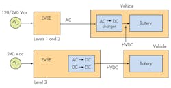
1. Level 1, 2, and 3 electric vehicle service equipment (EVSE) refers to the ac charging source that supplies the charger.
There are three basic types of EV chargers (Fig. 1). The electric vehicle service equipment (EVSE) refers to the ac charging source that supplies the charger. Level 1 chargers, built into the vehicle itself, are designed to operate from the standard available 120-V household ac power line. The onboard charger normally uses up to 12 to 16 A to generate 1.44 to 1.92 kW of power. This ac-dc charger has a charging time of about 17 hours, suitable for overnight charges.
A Level 2 charger is also onboard the vehicle, but can take advantage of 240-V ac service from the EVSE where available. This ac-dc supply can use from 15 to 80 A to produce 3.1 to 19.2 kW, and a has charging time of approximately eight hours. A dedicated 240-V ac line is required for Level 2 operation. Its limitation is the overall grid power available to the home or charger location and the time of availability.
The Level 3 charger supplies dc directly to the vehicle instead of ac. The dc voltage ranges from 350 to 700 V with a current up to 400 A. With power to the vehicle in the 120- to 240-kW range, the charging time reduces dramatically to 30 minutes or so. A large network of Level 3 charging stations will make EVs more widely acceptable.
Public EVSEs also feature communications capability, such as a connection to a building or other facility via Ethernet, RS-485, or cellular. In addition, most have a near-field communication (NFC) link for customer authorization. On top of that, residential EVSEs may incorporate Wi-Fi for monitoring and control.
A key part of the design is the connection between the charger and vehicle. This heavy-duty cable is terminated in a special connector known as the J1772. The connector is a Society of Automotive Engineers (SAE) standard for the U.S. It has five pins—three for the split-phase 240 V ac, one pin for the proximity signal detection, and a pilot signal. The proximity signal keeps the vehicle disabled while the charger is connected. The pilot signal is a two-way communications interface and protocol that negotiates between the battery status and energy available.
Other connectors have been adopted, such as the VDR-AR-ER-2623-2-2, a seven-pin connector used in Europe. It’s essentially an alternative to the J1772.
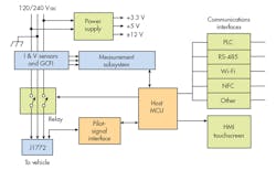
2. As seen in this simplified configuration of Level 1 and 2 EVSEs, incoming ac distributes to several points.
Three connectors have been designed for dc chargers. The most common is the CHAdeMO used for high-voltage dc. A pin is provided for CAN bus communications. The Combined Charging System connector adds two pins for high-voltage dc to the five pins compatible with the J1772. The CHAdeMO and Combined Charging System connector are in competition, either hoping it will be chosen as the standard Level 3 dc connector. In the meantime, the incompatibility is holding back Level 3 charger design. Tesla has its own proprietary Supercharger dc connector.
Charging Station Design
Charging stations are also called charge points or charging piles. A charging pile more often refers specifically to a fast dc charging station. In all cases, the hardware associated with a charging station is designated as the EVSE, as indicated earlier.
Figure 2 shows the main components of a Level 1 or Level 2 EVSE. The incoming ac is distributed to several places, starting with the power supply for the monitoring, control, and communications circuits. The ac line also feeds the sensor circuitry, where the current and voltages in the system are filtered and monitored. The ac is then passed through high-current contacts on a relay before appearing at the pins on the J1772 connector.
The monitoring, control, and communications circuits are managed by a main MCU. A human machine interface (HMI) with LCD touchscreen and controls, as well as one or more communications ports, round out the EVSE.
Figure 3 shows the main components of a Level 3 dc EVSE. The three-phase ac is subjected to conditioning by a power-factor-correction (PFC) circuit. The ac is also rectified by active MOSFET rectifiers into a high-voltage dc of about 400 V. This voltage is passed to a dc-dc converter made up of power FETs or IGBTs that generate the correct dc level for charging the battery. Multiple MCUs manage the monitoring and control, ac-dc/dc-dc power-conversion process, as well as the HMI with its LCD touchscreen and LED backlighting. Note the power-line communications (PLC) and CAN interfaces.

3. A Level 3 EVSE features multiple MCUs that manage monitoring and control, ac-dc/dc-dc power-conversion, and the HMI.
The Role of Communications
All EVSE stations use some form of communications to facilitate the charging process. In Level 1 and 2 EVSE, the pilot-signal port lets the ac source talk to the vehicle, its internal charger, and battery. The pilot port uses a ±12-V, pulse-width-modulated (PWM) 1-kHz signal to indicate the charge state and current available from the ac source. The duty cycle indicates the available current.
For example, an 8% duty cycle means 5 A is available, and 50% duty cycle indicates that 30 A is available. The pilot signal operates the relay that connects the ac to the vehicle. It disconnects the ac when the vehicle indicates that the charge is complete by way of the pilot signal.
Level 3 EVSE stations use either the CAN bus or PLC protocol, much like HomePlug uses OFDM. The RS-485 interface is also employed in some systems to communicate with an external system at a public station.
In addition, some systems can incorporate Wi-Fi. The Wi-Fi connection allows users to manage the charging process from any Wi-Fi-enabled device like a smartphone or tablet. This wireless link provides a way to automate the monitoring of the load profile and charging during off-peak hours. And using an appropriate app, you can schedule time at a public charging station.
Charging stations also exploit the NFC protocol for user authorization and payment. NFC uses a modulated 13.56-MHz signal to transmit and receive low-speed data over short distances. Most smartphones now leverage the benefits of NFC.

About the Author

Lou Frenzel
Technical Contributing Editor
Lou Frenzel is a Contributing Technology Editor for Electronic Design Magazine where he writes articles and the blog Communique and other online material on the wireless, networking, and communications sectors. Lou interviews executives and engineers, attends conferences, and researches multiple areas. Lou has been writing in some capacity for ED since 2000.
Lou has 25+ years experience in the electronics industry as an engineer and manager. He has held VP level positions with Heathkit, McGraw Hill, and has 9 years of college teaching experience. Lou holds a bachelor’s degree from the University of Houston and a master’s degree from the University of Maryland. He is author of 28 books on computer and electronic subjects and lives in Bulverde, TX with his wife Joan. His website is www.loufrenzel.com.
Comment About the Article
To join the conversation, and become an exclusive member of Electronic Design, create an account today!

Leaders relevant to this article: