External Load Diagnostics for Automotive Class-D Amplifiers

Download this article in PDF format.
Embedded electronics has continued to ramp up across the automotive landscape, taking on more substantial roles in many applications. One example is the presence of multiple class-D audio amplifiers within the system to implement radios, Bluetooth connections, and the like.
With greater dependence on electronic systems comes an increasing need to monitor their operation in order to detect potentially critical failures. Such monitoring can be done with load-diagnostic circuitry, which identifies potential faults that may occur in electrical circuitry throughout an automobile. This article explores the design of external fault-diagnostic circuitry intended to differentiate between various short-circuit conditions and provide speaker detection.
Another issue of concern is the increase in electromagnetic interference (EMI) within the vehicle. Innovative circuit design can help with this problem: For instance, a new four-channel class-D amplifier IC introduced in this article specifically takes on that challenge.
Common Faults
Most automotive audio systems use class-D switching amplifiers to operate the multiple speakers. Damage can easily result from improper interconnections or from valid faults in the equipment. The most common faults involve the misconnection of the class-D amplifier outputs and their speakers during manufacturing, testing, or servicing. These faults include:
- Short circuit to the positive supply line
- Short circuit to ground
- Short across the load
- Open circuit load (disconnected speaker)
How are these faults detected? The diagnostic circuit in Figure 1 was developed to look for and identify these common problems. The circuitry is connected across the speaker terminals. This can be done with a manual switch or via special electronic isolation switches that become permanently attached and turned on as needed. Inverters and reference voltages are used to sense the various connection errors and problems. The reference voltages indicated are derived from voltage dividers on a 12-V dc supply.
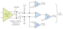
1. This fault-diagnostic circuitry for class-D amplifiers identifies output shorts, opens, and other conditions. (Courtesy of Texas Instruments)
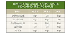
The fault is identified by observing the outputs of amplifiers 1, 2, and 3. These outputs are usually level converted and connected to an MCU designated for diagnosis duty. The table lists the diagnostic conditions detected.
Figure 2 shows the details of the isolation switch. When the input from the MCU is zero, Q3 is off and that causes both Q1 and Q2 to be non-conducting or open. Applying a logic 1 to Q3 turns it on and causes Q1 and Q2 to be biased on enabling fault detection.
Four-Channel Digital-Input Class-D Amp
As vehicles incorporate more and more electronic devices, they will likely become saddled with an even bigger cloud of electromagnetic interference (EMI). Class-D amplifiers can be a major contributor to vehicle EMI due to their switching nature. Yet with proper design, it’s possible to mitigate such EMI.
One electronic product that suffers most from EMI is the AM radio. Yes, AM radio. It’s still widely used because of its local news, weather, and traffic information. However, AM is hypersensitive to noise. One major source of that noise is harmonics generated by class-D amplifiers switching at frequencies in the 100- to 500-kHz range. The AM band runs from 535 to 1705 kHz, meaning that second, third, and fourth harmonics fall right into that frequency range, increasing noise level.
One solution that seems to have been ignored, up until now, is to set the class-D switching frequency above the AM band. It virtually eliminates the problem. On that front, Texas Instruments has introduced a new class-D amplifier IC that operates at 2.1 MHz. Beyond minimizing the EMI issue, the chip also allows for smaller inductors and capacitors in the output filter.
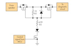
2. Here, an electronic isolation circuit is used with the fault-detection system in lieu of a mechanical switch. (Courtesy of Texas Instruments)
The TAS6424-Q1 is claimed the industry’s first 2.1-MHz class-D amplifier designed specifically for automotive infotainment applications. Supporting high-resolution 96-kHz digital input, this compact device enables high-fidelity audio with low distortion. The device permits the use of smaller external filters and eliminates up to 18 external components to reduce system size and cost compared to other class-D solutions. With max output power of 75 W/Ch, the amplifier features the industry’s highest switching rate, according to TI, and is the only audio amplifier that switches above the AM band.
Some of the specifications of the TAS6424-Q1 include:
- Audio inputs: 4-channel I2S or 4/8-channel TDM; supports sample rates of 44.1, 48, and 96 kHz; 16- or 32-bit formats
- Audio outputs: Bridge-tied load (BTL), including parallel; 75 W into 4 Ω at 25 V; 45 W into 2 Ω; at 14.4 V; 150 W into 2 Ω at 25 V with parallel BTL
- THD 10% with max power, <0.03% at 1 W.
- Built-in diagnostics
- Built-in protection
- Supply voltage from 4.5 to 26.4 V
- I2C control
- HSSOP 56-pin package measuring 18.41 × 7.49 mm
To help speed and simplify development, an evaluation module is available for the TAS6424-Q1.
About the Author

Lou Frenzel
Technical Contributing Editor
Lou Frenzel is a Contributing Technology Editor for Electronic Design Magazine where he writes articles and the blog Communique and other online material on the wireless, networking, and communications sectors. Lou interviews executives and engineers, attends conferences, and researches multiple areas. Lou has been writing in some capacity for ED since 2000.
Lou has 25+ years experience in the electronics industry as an engineer and manager. He has held VP level positions with Heathkit, McGraw Hill, and has 9 years of college teaching experience. Lou holds a bachelor’s degree from the University of Houston and a master’s degree from the University of Maryland. He is author of 28 books on computer and electronic subjects and lives in Bulverde, TX with his wife Joan. His website is www.loufrenzel.com.
Comment About the Article
To join the conversation, and become an exclusive member of Electronic Design, create an account today!

Leaders relevant to this article: