How Wide-Bandgap Devices Add Value in Bidirectional Power Conversion
Download this article in PDF format.
Most applications for power conversion involve a raw supply to be processed to a different stabilized voltage, often with galvanic isolation. Typical scenarios may include ac mains power-converted to low-voltage dc in a laptop adapter, or a discharging battery voltage in portable equipment boosted to a constant higher value. These are one-way conversions, but with increasing interest in alternative energy schemes and electric vehicles, there’s demand for power to be able to flow in both directions to harvest excess energy.
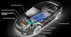
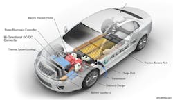
One example would be a PV installation where dc solar-panel power can be “fed back” into the ac grid when storage batteries are fully charged, with the ac in turn providing charge to the batteries at night through a bidirectional converter/inverter. Another situation is in electric vehicles, where a bidirectional dc-dc converter drops a main 400-V traction battery voltage down to 12 V for auxiliary equipment. The dc-dc reverses power flow from 12 V to 400 V under emergency conditions when the traction battery is dangerously low in charge (Fig. 1).
1. A typical EV battery system. (Image: All Rights Reserved, U.S. Department of Energy, https://afdc.energy.gov/vehicles/how-do-all-electric-cars-work)
When energy is being exchanged between batteries like this, the charging regime must be considered with the 12-V lead-acid cells requiring controlled current up to their fully charged condition and trickle current thereafter. In contrast, the 400-V string of lithium-ion cells needs very carefully controlled constant voltage.1 The converter control algorithms therefore must adapt to the direction of energy flow. One proposal being considered is to return traction battery charge to the grid through another bidirectional converter or inverter in a home charging station providing distributed grid energy storage.
Realizing a Bidirectional Converter
To be effective, energy harvesting must incur minimal losses, so power converters need to use techniques for best efficiency, which means additional complexity. Making the power converter bidirectional might seem more complex, so some designs are simply two separate converters in “anti-parallel” with sensing to energize one or the other. This may be an “easier” design, but it has the penalty of double the component count and consequent cost.
A much more elegant and cost-effective approach is to configure the same power components to operate in both directions, which isn’t as difficult as it might seem. Consider the case of a 400-V traction and 12-V auxiliary battery, bidirectional, isolated energy exchange. From 400 V to 12 V, the preferred power-stage topology is a full bridge that limits switch stress and uses the isolation transformer efficiently. The output is a bi-phase rectifier, which is preferred for minimum stress and component count, with the outline looking like Figure 2a.
2. Synchronous rectifiers configured for bidirectional power flow.
It may not be obvious how 12-V power can be converted to 400 V “in reverse,” but look at Figure 2b. As is normal anyway, the 12-V output diodes are replaced by synchronous rectifiers and the switches Q1-4 can be set OFF, leaving just their body diodes D1-4 effectively in circuit. A familiar circuit emerges when viewed from right to left—a current-fed push-pull power stage with a full-bridge output rectifier. None of the power components or magnetics have changed; they’re just controlled differently to set the direction of energy flow. Q1-4 can also be actively switched as synchronous rectifiers for better efficiency, although at 400 V, the current is lower and this may not be necessary.
Control of the power stages is key to the bidirectional functionality with dedicated chips now available.2 The control IC is often located on the low-voltage side as it can conveniently take startup power from the 12-V battery. If the high-voltage side is a phase-shifted full-bridge topology (PSFB), the controller can easily pass gate-drive signals across the isolation barrier through simple transformers. As the signals are always fixed width, just phase-shifted with respect to each other to provide regulation, the transformers have no problems with variable pulse width causing different peak positive and negative gate voltages.
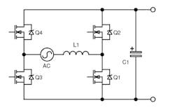
A similar exercise can be done with an ac-dc converter with an active bridge rectifier configured as the legs of an inverter for reverse energy flow. A modern technique is to use a “totem-pole” rectifier and power-factor-correction (PFC) stage, which lends itself nicely to be alternatively configured as an inverter (Fig. 3).
3. The “totem-pole” PFC stage can be configured as an inverter.
Wide-Bandgap Devices in Power Conversion
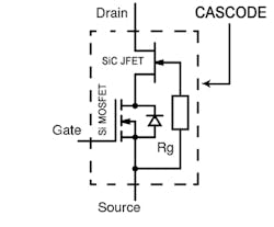
WBG, silicon-carbide (SiC), and gallium-nitride (GaN) semiconductors are now mainstream as replacements for silicon (Si) types. As switches, they have lower on-resistance, faster edge rates, and higher temperature operation than silicon. Discrete SiC diodes have no reverse-recovery charge and are available rated at high voltages. SiC switches are robust with high avalanche energy and excellent short-circuit current ratings, and they have a body diode that’s extremely fast. SiC MOSFETs are available as well as JFETs and cascodes—a “normally-off” combination of a Si-MOSFET and JFET with close to ideal switching characteristics (Fig. 4).
4. Cascode configuration of a Si-MOSFET and SiC JFET.
While WBG devices are finding their way into many power-conversion applications, they’re particularly suitable for bidirectional converters where efficiency and often size are major concerns. Fast switching edges result in low switching loss with high-frequency operation, which in turn allows for much smaller associated passive components, particularly magnetics.
If Q1-4 of the circuit in Figure 2b are implemented as synchronous rectifiers rather than setting them OFF and allowing body diodes to form rectifiers, the switches might be high-voltage Si-MOSFETs. Again, though, these would have higher conduction losses compared to SiC. High-voltage MOSFETs also have poor body-diode reverse-recovery characteristics, which can lead to device failures. SiC cascodes can be used which, although high-voltage-rated, have the equivalent body diode of a low-voltage Si switch with its very low forward voltage drop and fast recovery, again enabling low-loss operation.
Often, as a power stage, the full bridge Q1-4 will be operated with “phase-shift” control in a resonant mode (PSFB). This is currently the preferred mode for best efficiency above a few hundred watts and achieves zero-voltage switching (ZVS) at switch turn-on, with external inductance resonating with transformer capacitance and the switch output capacitance COSS. SiC devices, particularly cascodes, have a very low value for COSS, enabling a relatively low value of external inductance for resonance. This helps increase duty-cycle range and/or the maximum switching frequency.
SiC and Bidirectional Power Conversion Complement Each Other
As has been explained, SiC devices complement bidirectional power-conversion techniques and have parameters that enable low losses—a vital feature in applications that harvest energy such as PV and EV battery systems. A wide range of SiC diodes, JFETs, and SiC FET cascodes are available from UnitedSiC with a wealth of helpful application data.
Jonathan Dodge, P.E., is Senior Applications Engineer at UnitedSiC.
References
1. https://batteryuniversity.com/index.php/learn/article/charging_lithium_ion_batteries
About the Author
Jonathan Dodge
Senior Applications Engineer
Jonathan Dodge is a Senior Applications Engineer at UnitedSiC. He received a BSEE in Electrical and Electronics Engineering from Oregon State University in 1992, and an MSEE in Electrical Engineering from The University of Idaho, with an emphasis in power electronics and digital design, in 2000. Jonathan has experience in automated manufacturing testing, analog, digital, and power electronics spanning 1.5- to 500-kW power levels.


