More Availability of Faster Charging Stations Makes EVs Irresistible
Download this article in PDF format.
Let’s face it, electric vehicles (EVs) are in our future. Virtually all automotive manufacturers have developed EV models or pledged to develop new EVs soon. After a 100 or more years of internal combustion engine (ICE) domination, manufacturers are finally letting go and committing to an EV future.
Breaking up is hard to do, so they say. But the green movement, government regulations, and the concessions of the buying public are pushing the world to EVs despite the continued abundance of fossil fuel and the significant positive improvements in the ICE.
Sponsored Resources:
- Maximizing power for level 3 EV charging stations
- Designing highly efficient, powerful and fast EV charging stations
- Spend less than 30 minutes at an EV charging station
The Roadblocks
Other than the billions of dollars needed for an auto manufacturer to convert from an ICE-based product line to an EV-based lineup, the two main arguments against EVs has been their limited range and the long battery-charging time. The typical ICE vehicle has a range of up to 400 miles before fill up. And there are tens of thousands of gasoline stations to help extend that range.
Most EVs have difficulty making 100 miles on a charge, but newer models with better batteries can now achieve over 200 miles before a recharge and 300 miles is sure to become commonplace. Continued battery development will boost that range in the near future.
Another factor in the consumer’s “range anxiety” is the limited number of charging stations. Short range may be acceptable if plenty of recharge stations are around. Currently there are some, but not enough. To make EVs viable, the number of charging stations should be equivalent to the number of gasoline stations available to us today. Work is under way to make that happen.
One such example is Ford’s recent announcement that it has partnered with Electrify America and Greenlots to develop a national EV charging network. To be called the FordPass Charging Network, it will be made up of 12,000 charging stations with up to 35,000 plugs. These stations will feature the high-power dc charging capability that will speed up recharging. Today, it still takes about 30 minutes, even with high-voltage dc, to fully recharge. Who wants to wait that long when a gasoline fill-up rarely takes more than about 10 minutes?
Once the public is fully aware of those thousands of fast charging stations, sales of EVs should soon increase considerably.
Better Power Electronics is the Solution
The primary need for all those high-voltage dc charging stations is low-cost, highly efficient ac-dc and dc-dc converters that greatly speed up recharge. These chargers connect directly to the auto’s main drive battery, which delivers 400 V or more to the main drive motors. Recharging a battery like that requires many kilowatts of power. Such chargers—referred to as Level 3 chargers—connect directly to the three-phase ac power line.
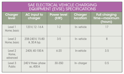
The automotive industry and the Society of Automotive Engineers (SAE) have established some formal definitions for EV chargers often referred to as electric vehicle supply equipment (EVSE). The table summarizes these types of chargers.
Level 1 and 2 chargers, built into the vehicle, are called on-board chargers (OBCs). Single- or two-phase home ac provides the power. Charging times are lengthy for Levels 1 and 2, but acceptable for overnight charging.
Level 3 chargers are for public charging stations. With three-phase grid power input, significantly faster charging times are possible. Level 3 chargers deliver dc directly to the batteries. With an output in the 200- to 800-V range and current levels up to 400 A or so, charging time is drastically reduced. Level 3 chargers, which are said to charge a battery to 80% capacity in 20 minutes, are the solution to a healthy EV future.
DC Charger Architecture
Figure 1 shows a generic diagram that helps to imagine a Level 3 charger. It takes in the three-phase ac from the power grid, filters it, and then provides power factor correction (PFC). The ac is rectified to dc. A dc-dc converter develops the desired high-voltage dc that connects to the battery. An embedded MCU controls the whole thing, including the PFC implementation and the gate drivers for rectifiers and conversion circuits. The actual circuitry is much more sophisticated.
1. Here’s a simplified view of a Level 3 charging station.
Figure 2 illustrates typical circuitry. The ac input is applied to a Vienna rectifier circuit used for PFC as well as rectification. Pulse-width modulation (PWM) from the controlling MCU switches the MOSFETs such that rectification occurs and the power factor is corrected.
2. The diagram provides circuit details of the charger from ac in to battery voltage out.
The high-voltage output is applied to two resonant dc-dc converters in parallel that develop the output voltage for charging the battery. The converter MOSFETs are driven by PWM signals from the microcontroller. The transformer coupling between the full-bridge circuits provides the necessary isolation between input and output.
Notice in Figure 2 that the output stages are in parallel. To scale up the output power for faster charging, most dc-dc converters like this can be stacked or further connected in parallel. With this arrangement, a wide range of power levels can be accommodated.
Implementing Level 3 Chargers
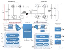
A good starting point for your Level 3 charger design is Texas Instruments’ TIDA-010054 Dual Active Bridge reference design. Figure 3 shows the circuit and related parts such as the silicon-carbide (SiC) gate drivers.
3. The schematic shows the complete circuit of the TIDA-010054 reference design.
This single-phase, dual-active-bridge (DAB) dc-dc converter consists of these sections. The left side is the high-voltage bridge from the Vienna rectifier/PFC (700 to 800 V). The right side is the dc-dc circuit that charges the battery (380 to 500 V). This arrangement allows for stacking converters to achieve high power throughput and facilitate a bidirectional mode of operation to support battery charging and discharging applications.
Some of the key features of this design are:
- Soft switching commutations
- Efficiency is in the 97% to 98% range
- Isolated voltage and current sensing
- Galvanic isolation
- TI’s C2000 MCU TMS320F280049 controller for digital control
- Maximum power output of 10 kW
- SiC MOSFET devices
The critical components in these converters are the switching transistors. Older designs used bipolar junction transistors (BJTs), but these were soon mostly replaced with MOSFETs. Next came super MOSFETs. What these devices could not handle, like the very high voltages and currents involved, were able to be handled by IGBTs.
Today, the trend is to use the even more versatile SiC MOSFETs. These devices can easily manage voltages up to 1000 V or more at high current levels. And they switch faster (up to 100 kHz) and have a lower on-resistance, which helps boost efficiency.
The trend in charging station design is to use dc-dc converters that can handle a two-way power flow. This arrangement permits flexible arrangements within the vehicle for other charging and load powering applications. A desirable feature is the vehicle-to-grid (V2G) mode that lets the vehicle battery send power back to the grid.
Sponsored Resources:
About the Author

Lou Frenzel
Technical Contributing Editor
Lou Frenzel is a Contributing Technology Editor for Electronic Design Magazine where he writes articles and the blog Communique and other online material on the wireless, networking, and communications sectors. Lou interviews executives and engineers, attends conferences, and researches multiple areas. Lou has been writing in some capacity for ED since 2000.
Lou has 25+ years experience in the electronics industry as an engineer and manager. He has held VP level positions with Heathkit, McGraw Hill, and has 9 years of college teaching experience. Lou holds a bachelor’s degree from the University of Houston and a master’s degree from the University of Maryland. He is author of 28 books on computer and electronic subjects and lives in Bulverde, TX with his wife Joan. His website is www.loufrenzel.com.


