Networking in Automotive Body Control Modules
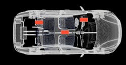
Automotive body control modules (BCMs) are present in all modern vehicles to handle comfort, security, and lighting functions (Fig. 1). They have quickly transformed over the last few years, driven by the growing number of features, the desire to replace fuses and relays, the increased bandwidth requirements on in-vehicle networks, and the shrinking size requirements of original equipment manufacturers (OEMs).
1. The next generation of automotive body control modules (BCMs) provides a wide range of connectivity.
This article reviews the evolution of networking in BCMs, how different vehicle architectures affect in-vehicle networks, and common networking interfaces and requirements.
Vehicle Architectures
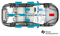
The increasing automotive body loads distributed around the vehicle have created control, load, and networking issues. Some solutions control the loads from one central module; others control each load or a subset of loads locally. This creates a range of possible vehicle architectures.
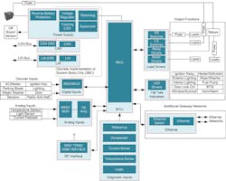
The body-domain architecture integrates most body functions into one large central-control module, including a message-routing central gateway (Fig. 2). In addition, this centralized architecture often requires a large number of low- to mid-bandwidth control buses like local interconnect network (LIN) and controller area network (CAN). It’s becoming common to have more than a dozen LIN networks and more than eight CAN networks in a centralized BCM-plus-gateway application.
2. The body-domain architecture integrates a majority of body functions into one large central-control module.
It’s also common to see interfaces like Ethernet used as the high-bandwidth interface in centralized BCM-plus-gateway modules. Ethernet enables the distribution of large amounts of data around the vehicle between different domain controllers or to external tools.
Other body-domain architectures decentralize the body domain, with multiple smaller distributed BCMs around the vehicle. For example, in the three-BCM architecture (Fig. 3), one BCM is placed in the rear of the vehicle, a second goes in the center of the vehicle, and a third is in the front of the vehicle. Placing multiple modules around the vehicle enables you to locate them closer to the inputs that need monitoring and the loads that need controlling. This can often result in simpler wiring, with only power and networking shared between control modules.
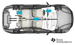
3. A three-BCM architecture has one BCM in the rear of the vehicle, a second in the center, and a third in the front. Placing multiple modules around the vehicle places them closer to the inputs that require monitoring and the loads that need controlling, resulting in simpler wiring.
By handling a smaller number of inputs and a smaller number of loads, these modules can also be simpler from both a power and networking perspective, containing just a single regulator and a single interface, such as LIN or CAN.
Populating and depopulating transceiver integrated circuits and using single, dual, and quad transceivers to optimize solution size scales the number of interfaces on the BCMs so tthat hey can be used across different car platforms or trim levels.
Vehicle Interfaces
To optimize the complexity and cost of in-vehicle networking, a number of interfaces have been developed over the years.
LIN
In direct response to the growing integration of small electronic comfort features into vehicles, the first LIN standard was released in 1999. The idea was to offer a single-wire, low-cost, low-speed interface that could be implemented on a small microcontroller with a simple universal asynchronous receiver transmitter peripheral (Fig. 4).

4. LIN targets human-machine interface applications where latency on the order of tens of milliseconds is more than tolerable.
LIN targets human-machine interface applications where latency on the order of tens of milliseconds is more than tolerable. The master module is responsible for polling the status of each slave on the network on a pre-defined schedule. With one central master node on the network handling all scheduling, syncing, and clocking, the slaves can be as low cost as possible. Master multi-slave polling networks lower the total system cost. However, the delay for an event to be processed can be a maximum of the time it takes to run through the full schedule table.
Since there are master and slave modules, some of the key transceiver features will depend on the role the transceiver will have on the network. For example, most slave modules need to respond to a LIN wakeup signal broadcasted over the bus. This can require a low-power wake receiver and an inhibit (INH) output pin for enabling and disabling a local regulator. It would allow slave nodes to be in the lowest possible power state, with only the transceiver monitoring the LIN bus and reducing system supply current while the vehicle is off.
On the other hand, a LIN master module is responsible for broadcasting the wakeup signal and therefore doesn’t need a low-power wake receiver and INH output pin. BCMs often connect to large numbers of LIN clusters, thus necessitating many LIN master transceivers. For BCM applications like this, it’s important to have transceiver families with single, dual, and quad product offerings to easily scale designs in a size-optimized manner.
In order to earn OEM approvals, other important features include the ability to handle radio-frequency (RF) immunity, transient, and electrostatic discharge, and to have low emissions. Depending on the vehicle type, you may also need different bus-fault protection voltages. For example, 12-V passenger vehicles require bus-fault protection voltages of up to 40 V, but 24-V commercial vehicles like semi-trucks and buses require higher bus-fault protection voltages of up to 60 V or more.
CAN
CAN started in the 1980s and has continued to evolve. Used by OEMs worldwide, CAN is a tried-and-true distributed control, serial, two-wire differential network standard developed for automotive and industrial applications. A differential topology leads to a more robust interface that’s less susceptible to RF interference and has lower emissions due to the balanced differential signaling (Fig. 5).

5. CAN is a multi-master protocol with nondestructive, bit-wise arbitration.
CAN is a multi-master protocol with nondestructive, bit-wise arbitration. Any CAN node on the network can access the bus when it’s idle; if multiple nodes try to do so at the same time, the higher-priority message will win arbitration without any data errors. Other important features of the CAN standard include error checking, fault confinement, and clock synchronization.
Classical CAN, as the original International Organization for Standardization (ISO) 11898 CAN standard is often referred to now, has a maximum data rate of 1 Mb/s and a maximum data payload of 8 bytes. As with the LIN bus, fault protection, transient protection, electromagnetic compatibility (EMC) performance, and packaging options are key differentiators.
CAN with Flexible Data Rate
Continuing along the trend of increasing bandwidth for in-vehicle networks, in 2012, CAN in Automation (CiA) proposed updates to the CAN standard to allow for faster data rates and larger payload sizes. Now known as CAN with Flexible Data Rate (CAN FD), the updates were ratified into new versions of the ISO 11898 standard.
CAN FD makes three major changes to the CAN standard:
- The maximum data rate increased from 1 Mb/s to 5 Mb/s.
- The maximum payload size increased from 8 bytes of data to 64 bytes of data.
- Updated algorithms for cyclic redundancy checking.
CAN FD is still backwards-compatible with classical CAN (Fig. 6). It has benefits of the increased data rate and payload size.
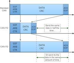
6. CAN FD, which is still backwards-compatible with classical CAN, has an increased data rate and larger payload size.
Taking advantage of these benefits requires new CAN FD controllers for handling the updated protocol and new CAN FD transceivers to handle the more stringent physical-layer requirements. Nevertheless, a 5X increase in bandwidth and much lower effective overhead with the larger payloads have led OEMs worldwide to quickly adopt CAN FD.
As with classical CAN, bus-fault protection, transient protection, EMC performance, and packaging options are still key differentiators.
CAN with Partial Networking
As worldwide vehicle-emissions requirements become more stringent, OEMs are exploring ways to reduce vehicle weight and energy consumption. To address lower system-wide vehicle power consumption, a third version of CAN was created, CAN with Partial Networking (CAN PN).
CAN PN added the ability to have a subset of nodes on a CAN network active while allowing other nodes on the network to remain in low-power mode. This is different from classical CAN and CAN FD, since all nodes on a network are either active or in low-power mode.
CAN is set up as a broadcast topology: All nodes are required to check the validity of a transmitted frame and respond with an acknowledge bit. In practice, this means that if one node on a network sends a message, every other node on the network is required to wake up and error-check that message.
Allowing nodes to remain in low-power mode until specific identifiers or payloads are broadcasted over the network enables OEMs to create a large variety of partial networks. Programming each node with only the messages important to it allows more nodes to remain in low-power mode, and thus reduces the vehicle’s current consumption.
CAN PN has the same requirements as CAN and CAN FD, but also requires an accurate low-power oscillator and built-in digital logic for decoding broadcasted CAN messages.
Ethernet
Unlike LIN and CAN, the Ethernet standard started as an industrial protocol and was well established worldwide before ever being considered for the automotive space. When 1- to 10-Mb/s data rates were no longer sufficient, automotive OEMs and suppliers looked to Ethernet. The Institute for Electrical and Electronics Engineers (IEEE) has a family of Ethernet standards called IEEE 802.3.
OEMs’ desire to minimize the weight and emissions of any protocol used in automobiles led to the creation of two new standards specifically for automotive applications. Using new encoding schemes and transmitters and receivers capable of full-duplex operation reduced the wiring from two or four twisted pairs to a single twisted pair (Fig. 7).
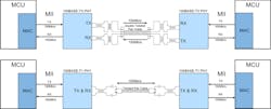
7. Ethernet normally uses four wires, but automotive Ethernet employs only two.
The first automotive standard released was the 802.3bw standard, which is also known as 100Base-T1. It has that name thanks to its 100-Mb/s data rate and ability to communicate full-duplex over a single unshielded twisted-pair cable (T1). The standard specifies that the transceivers must be able to support a minimum of 15 m; today, many transceivers support 30 m or more.
To further increase the bandwidth of the bus by another 10X, the IEEE 802.3 working group ratified the 802.3bp standard in 2016. This standard is also referred to as 1000Base-T1, since it allows for 1,000 Mb/s over a single unshielded twisted pair of cable.
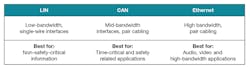
8. LIN, CAN, and Ethernet provide complementary functionality.
One limitation of Ethernet is that it is a point-to-point standard; an Ethernet switch in the physical layer is necessary if one node needs to communicate with multiple other nodes. But because 100Base-T1 and 1000BASE-T1 are ac-coupled to the bus, the fault-protection voltage doesn’t need to be as high as LIN and CAN (Fig. 8). Furthermore, low emissions, high RF immunity, and the ability to communicate over longer distances are differentiators for Ethernet transceivers.
John Griffith is an Analog Engineer at Texas Instruments.

About the Author
John Griffith
Field Applications Engineer
John Griffith is an experienced analog engineer with a demonstrated history of working in the semiconductor industry. He has worked in the automotive electronics industry for since 2011 with experience in semiconductor product support and definition, as well as PCB schematic capture, design, and layout. John holds Bachelor's and Master's degrees in Electrical Engineering from the Rochester Institute of Technology.
Comment About the Article
To join the conversation, and become an exclusive member of Electronic Design, create an account today!

Leaders relevant to this article: