Download this article in PDF format.
In case you haven’t noticed, automotive electrical systems are undergoing a significant change from the old 12-V systems to a new hybrid 12- and 48-V system. The number of new electrical and electronic devices and subsystems added to new vehicles over the years has significantly increased the electrical load on the old, reliable lead-acid 12-V battery. And the breaking point has arrived.
In addition, hybrid electrical vehicles (HEVs) and full electrical vehicles (EVs) are gradually gaining acceptance. HEV/EVs need an even more aggressive electrical system. This article explores the new systems that more adequately deal with the modern electronic needs of the modern automobile.
Sponsored Resources:
- Taking charge of electric vehicles – both in the car and on the grid
- System Power Architectures in Body Control Modules
- Bridging 12V and 48V in dual-battery automotive systems
The Emerging 12/48-V Dual-Battery Electrical Systems
The end is near for the long-lived 12-V electrical system in vehicles. First appearing in 1955, the 12-V system replaced older 6-V systems. Now, 60+ years later, that system has reached its limits. With the continuous inclusion of new electronic systems over the years, the total electrical demands in a car’s traditional 12-V electrical system exceed its capability. For example, at low temperatures, the static-load components can account for all of the power generated by the alternator. And more new loads are still to come.
The solution to this problem has been known for years. In the early 2000s, a 36/42-V system was proposed though never adopted. Getting the whole auto industry to adopt a new system isn’t easy, but now there’s no choice. A dual 12- and 48-V system is the solution. The strategy being employed by automakers is to move power-hungry vehicle components and subsystems to a new 48-V rail powered by a lithium-ion battery.
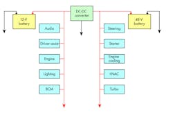
The new electrical system looks like that in Figure 1. The loads are divided with the most power-hogging systems on the 48-V bus and lesser loads on the 12-V bus. The heaviest loads are from the starter, water and fuel pumps, HVAC, cooling fan, and body-stabilization systems. The availability of a 48-V source makes possible enhancements like electrical turbochargers that are far more effective than the exhaust-driven type. Besides providing much more power in general, up to about 10 kW, the 12/48-V system means lower currents that result in smaller lighter cables.
1. Shown is the architecture of a dual 12/48-V battery system in new vehicles.
In Figure 1, you will see the dc-dc converter, which is the key to making this dual system practical. The converter provides for a bidirectional-power-transfer capability that keeps both sources of power alive under all conditions. This arrangement will charge either battery from the other if it’s discharged and meet temporary overload conditions.
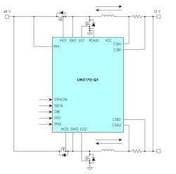
While a pair of dc-dc converters would work—one buck for 48 V to 12 V and a boost for the 12 V to 48 V—it’s possible to create a bidirectional buck-boost converter. One way to implement such a system is to use Texas Instruments’ LM5170-Q1, a multiphase bidirectional current controller IC. This buck-boost controller forms the core of a bidirectional converter for 12/48-V systems. It manages the current direction and average current with a pulse-width-modulation (PWM) control scheme under the direction of an MCU.
Figure 2 shows a simplified version of the bidirectional dc-dc converter using this IC. An evaluation board and reference design (TIDA-01168) using this chip are also available.
2. This bidirectional dc-dc converter for dual-battery voltage systems uses the LM5170-Q1. Some external components have been omitted for clarity.
Powering Vehicle Body-Control Modules
All automotive electrical systems divide up related electrical loads into segments. Examples are separate loads for engine, transmission, ADAS, infotainment, and brakes. The loads operate from the 12-V battery and vary from manufacturer to manufacturer.
One load that all systems implement is body electronics, which is handled by the body-control module (BCM). The specific loads handled by the BCM also vary by manufacturer. Most of them cover things like power windows and door locks, windshield wipers, and lighting. The MCU-controlled BCM is made up of a mix of dc-dc converters, LDO regulators, LED drivers, and a variety of sensors and switches. Typical load voltages are in the 1.2- to 5-V range.
The BCM starts with the battery output that’s loaded with noise and transients. Some EMC filtering and battery-protection components prep the voltage for some regulators that generate the needed rail voltages. For small BCMs, an all-LDO architecture is used. The LDOs further clean and regulate the 12 V down to several lower-voltage buses. LDOs aren’t the most efficient of regulators, but with light loads they’re preferred. With loads greater than about 400 mA, the heat and inefficiency may make the LDO approach unacceptable.
Another approach is to use a combination buck switching regulator followed by LDOs. It’s more efficient. The buck regulator usually creates a 5-V bus; following LDOs make up any lower-voltage buses.
An alternative arrangement is to start with a buck converter followed by a boost converter and another buck regulator. The boost converter controls the voltage so that some loads can operate under cold-crank conditions and/or operate the engine start/stop feature implemented in many new vehicles. Under such conditions, the battery voltage drops drastically, so regulation is critical. Additional buck converters are also used to generate the other needed lower-voltage buses.
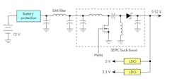
A good choice for the buck/boost approach is to use a SEPIC-type converter. The SEPIC is a combination buck/boost architecture that’s efficient and flexible. It can then be followed with additional converters or LDOs as needed (Fig. 3).
3. Here’s a simplified BCM automotive power supply using a SEPIC buck-boost converter.
EV Battery-Charging Solutions
EVs and HEVs both require battery-charging systems. Some of the chargers are internal to the vehicle while others are external, either at home or a commercial charging station. The only thing keeping EVs from completely dominating auto sales is the constant need for battery charging, the dearth of commercial charging stations, and the limited range of the vehicles themselves. Fast, reliable battery charging is the key to EV eventual success.
So, let’s take a look at onboard chargers, how they work, and why they’re used. Also discussed are charging stations and how they interact with onboard charger and EV battery-management systems (BMS).
All EVs and HEVs have an onboard charger for the main HV drive battery. It takes the ac from a home or commercial charging station and conditions it into dc to charge the battery. The charging station hardware is typically referred to as the electric-vehicle service equipment (EVSE). The other form of external charger is a dc source that connects directly to the HV battery and provides a rapid recharge.
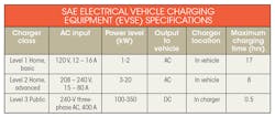
Three classes or levels of vehicle charging have been defined by the Society of Automotive Engineers (SAE) (see table). Level 1 and 2 chargers are built into the vehicle itself. Level 3 chargers are defined primarily for public charging stations.
Other organizations also define charging-related standards. The International Electrotechnical Commission (IEC) defines four charging modes. In addition, four charger connection plugs have been specified. Added to all that are the many governmental safety codes/standards and regulations related to EMC, efficiency, and safety.
Figure 4 shows a generalized EVSE powering an onboard charger. The EVSE equipment conditions and controls the AC while communicating with the vehicle a CAN bus connection (COMMS). The onboard charger first performs power factor correction (PFC) on the ac to keep the input current in phase with the ac mains voltage to meet the power-factor requirements of the regulations. A DC-DC converter then develops the output to charge the battery.
4. The generic content of an EVSE Level 2 charger that supplies ac to the vehicle.
Figure 5 shows a Level 3 charger. The three-phase ac input undergoes PFC to produce an acceptable power factor. That ac then goes to an ac-dc converter to generate the high voltage (HV) that charges the HV battery directly. Output voltage is in the 300- to 800-V range. A separate low-voltage supply powers the remaining circuitry, including the MCU and COMMS.
5. An EVSE Level 3 HV dc charger is used for faster charging.
All of these chargers are controlled by an MCU, and the power-conversion circuits are of the switch-mode variety to ensure maximum efficiency.
Sponsored Resources:
About the Author

Lou Frenzel
Technical Contributing Editor
Lou Frenzel is a Contributing Technology Editor for Electronic Design Magazine where he writes articles and the blog Communique and other online material on the wireless, networking, and communications sectors. Lou interviews executives and engineers, attends conferences, and researches multiple areas. Lou has been writing in some capacity for ED since 2000.
Lou has 25+ years experience in the electronics industry as an engineer and manager. He has held VP level positions with Heathkit, McGraw Hill, and has 9 years of college teaching experience. Lou holds a bachelor’s degree from the University of Houston and a master’s degree from the University of Maryland. He is author of 28 books on computer and electronic subjects and lives in Bulverde, TX with his wife Joan. His website is www.loufrenzel.com.
