A Spell to Correct Erroneous Missile Tracking Data
Get the complete compendium of troubleshooting articles. Download Now in PDF Format.
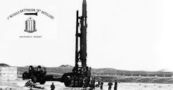
In the Cold-War days of the early 1960s, I was assigned to a Corporal guided missile unit that guarded the Fulda Gap, a likely Soviet armor invasion route. We spent many days in the field, responding to “Alerts,” which sent our units into the German countryside to conduct preparations to fire a missile.
Fortunately, the order to fire never came.
Central European weather was not easy on equipment, so my repairmen were busy. The Corporal missile guidance system was a primitive all-analog system; the ground guidance computers consisted of 26 chopper-stabilized op amps!
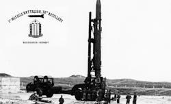
The missile trajectory was tracked by a radar, which fed the data to this computer to be used to guide it to the target. Position information was derived by precision potentiometers on the azmuth (AZ) and elevation (EL) axes of the tracking antenna and these voltages were routed to the computer through a large cable to the radar van and then to the guidance van.
For such an early system, it worked pretty well but it depended on very skilled crews.
One afternoon on an alert in the forest of Wasserlos, the radar operators reported a problem with the position data from the antenna--the position readout voltages were wrong--very wrong! They did the usual troubleshooting, checking the cable connectors to make sure they were tight and even replacing the antenna-to-radar-van cable with a spare without success.
Our Ordnance detachment was called in to track down the problem. After listening to the operators' description of their attempts to troubleshoot their situation and seeing the crazy position voltage readings for ourselves, we decided to start at the source, the position readout potentiometers themselves.
By disconnecting the connector from the antenna pedestal, we could measure the resistance across the pot and to the wiper arm as we manually moved the antenna in AZ and EL. Okay, that eliminated the antenna as the source of the problem so we moved along, replacing the connector and pulling the connector off the other end, a large feedthrough bulkhead mounted in a below-floor-level well on the bottom of the radar van. Checking the resistances with a VOM at this end showed the proper readings which eliminated the cable as the problem.
Plugging that connector back in showed that the problem was still there! Subsequent checks eliminated the radar van to computer van cable path so there wasn't much left to check.
Out of desperation more than anything, I removed the connector from the bulkhead connector inside the van itself and measured the resistance back to the antenna potentiometers. These readings were not correct, in fact they were crazy!
What was going on? The only thing between the antenna cable connector, which I knew was okay, to the pins of the bulkhead connector was the connector itself. What could go wrong with a connector? Disconnecting everything I checked the pins for an open or a short--nothing!
Then I switched the VOM to a higher range and checked the resistance across the pins that carried the AZ pot wiper voltage: 20k ohms! Across the EL pot read 20k. What? In fact, between any pin and any other pin in this big multi-pin bulkhead connector, the VOM read 20k.
This was really strange, I had to find out what was causing this weird resistance reading. With help from the operators, I removed the bulkhead connector and disassembled it. Inside there was a rubber seal that all pins projected through and underneath that was a phenolic block. Under the rubber seal there was a thin layer of black mold! This was the culprit that caused all the problems.
Scrubbing the connector and seal clean and giving it a coat of DC-3 silicone grease solved the problem. We were back up and operational-- Western Europe was safe for another day.
From that experience I learned about “sheet rho” and that the resistivity of black mold was 20k/square.
At the time of this incident, Neil Albaugh was Section Chief of the 157th Ordnance Detachment in Babenhausen, Germany. After a long and rewarding career in industry, he is now an analog consultant.
NOTE: This article was submitted as an entry in Electronic Design's Halloween 2018 "Double, Double, Toil and Troubleshooting" Contest.
About the Author
Neil Albaugh
Analog Design Consultant
Neil Albaugh provides analog design consulting speciallize in electro- optical circuits and systems and precision instrumentation.
Comment About the Article
To join the conversation, and become an exclusive member of Electronic Design, create an account today!

Leaders relevant to this article: