Good Crimps And How To Recognize Them
This article was originally published in the February 5, 1996 print issue of Electronic Design and was written by RANDY KEMPF, director of product marketing at Molex. Randy holds a BSEE degree from Purdue University, W Lafayette, Ind., and an MBA degree from the University of Iowa, Iowa City. This online version was restored and edited by Andy Turudic.
You’ve waded through all of the connector catalogs and found the connector that meets all your design criteria and is just right for your application. It has the right current rating, voltage rating, circuit size, engagement force, wire-size capabilities, configurations, and termination method. It has all of the safety features you need: positive locks, fully-isolated contacts, polarization, and agency certifications. It is, in short, the perfect connector.
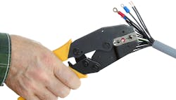
But don’t let out a huge sigh of relief quite yet—especially if the connector you’ve chosen uses a crimp-termination system. Crimps can be one of the fastest, most reliable, and rugged termination methods. But if the terminal isn’t crimped onto the wire correctly, it’ll wipe out all of the hard work you put into selecting the right connector. And, although there are 13 common crimping problems that can reduce the reliability of your product, these problems are easy to avoid with a little knowledge and advance planning (see “A guide to crimping problems,” below).
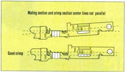
To begin with, it helps to understand that a terminal has three major sections: mating, transition, and crimping (Fig. 1). The mating section, as the name implies, is the section of the terminal that mates, or becomes the interface, with the other half of the connection. This section was designed to mate with a terminal of the opposite gender and to perform in a certain manner by the connector’s designer. Anything that you do that deforms the mating section, especially during the crimping process, will only reduce the connector’s performance.
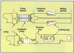
The crimp section is the only section that’s designed to be affected by the crimping process. Using termination equipment recommended by the connector manufacturer, the crimp section is deformed so it can be securely attached to a wire. Let’s look at an example of a properly performed crimp (Fig. 2).
The insulation crimp compresses the insulation without piercing. The wire strands (or brush) protrude through the front of the conductor crimp section by at least the diameter of the wire’s conductor. For example, an 18 AWG wire would protrude at least 0.040 in. Both the insulation and conductor are visible in the area between the insulation and the conductor’s crimp section. The crimp section shows a bellmouth shape in the leading and trailing ends, while the transition and mating sections remain exactly as they were before the crimping process.
If your crimped terminal doesn’t look like the terminal in Figure 2, it may be that something went wrong during the crimping process. Here are 13 of the most common problems that may occur during the crimping process and how to avoid them.
Crimp height is too small: The crimp height, which is the cross-sectional height of the conductor’s crimp section after it's been crimped, is the most important characteristic of a good crimp. The connector manufacturer provides the crimp height for each wire size for which the terminal was designed. The correct crimp height range or tolerance for a crimp section may be as small as 0.002 in. With a specification this tight, verifying that the press is set up correctly is very important for achieving a good crimp.
A crimp height that’s either too small or too large won't provide the specified crimp strength (terminal retention to the wire), will reduce the wire pull-out force and current rating, and may generally cause the crimp to underperform in otherwise normal operating conditions. A crimp height that’s too small also may cut strands of the wire or fracture the metal of the conductor crimp section.
Crimp height is too large: crimp height that’s too large won’t compress the wire strands properly. The result is excessive voids in the crimp section because of a lack of metal-to-metal contact between the wire strands and the metal of the terminal.
The solution to crimp-height problems is very simple: Adjust the conductor crimp height on the crimp press. Using a caliper or micrometer as shown in Figure 2, verify that the crimp height is within specification when the press is first used for a production run. Then re-check it as needed.
Insulation crimp is too small or too large: Connector manufacturers don’t typically supply a crimp height for the insulation because of the variety of insulation types and thicknesses. The insulation crimp provides a strain relief for the conductor crimp section so that as the wire flexes, the wire strands don’t break. An insulation crimp section that’s too small may overstress and weaken the metal in the insulation crimp section. Most types of crimp tooling allow the insulation crimp height to be adjusted independently of the conductor crimp height. The correct adjustment allows the terminal to grip the insulation for at least 180° without piercing the insulation. An insulation displacement, or compression where the outside diameter (OD) of the terminal’s insulation crimp and the OD of the insulation are about the same, is ideal.
Loose wire strands: This is another common cause of crimping problems. If all of the wire strands aren’t fully enclosed in the conductor crimp section, both the strength of the crimp and its current-carrying capability may be greatly reduced. To get a good crimp, you need to meet the crimp height specified by the connector’s manufacturer. If all of the strands aren’t contributing to that crimp height and therefore, crimp strength, then the crimp won’t perform to specifications. Generally, the problem of loose wire strands is very easy to solve by simply gathering the wires back into a bunch before inserting them into the terminal to be crimped. The strands may have been inadvertently separated during the handling or bundling process if stripping the insulation from the wire is done separately. Using a “strip-and-retain” process for insulation removal, in which the insulation slug isn’t fully removed from the wire until just before a terminal is crimped onto the wire, helps minimize the problem.
Strip length is too short: If the strip length is too short or if a wire isn’t fully inserted into the conductor crimp section, the termination may not meet the specified pull force because the metal-to-metal contact between the wire and the terminal is reduced. As shown in an figure, the strip length of the wire is too short (note that the insulation is in its proper position), not allowing the required one-wire-OD extension in front of the conductor crimp section (Fig. 3). The solution is simple: increase the strip length.
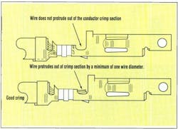
Wire is inserted too far: Another crimping problem that relates to a too-short strip length occurs when the wire is inserted too far into the crimp sections. As a result, the insulation is too far forward of the insulation crimp section and the conductors protrude into the transition section.
This may cause as many as three failure modes in the actual application. Two relate to a reduced current rating and/or wire pull-out force because of reduced metal-to-metal contact in the conductor crimp section. A metal-to-plastic contact isn’t as strong as a metal-to-metal contact. And even more importantly, it doesn’t conduct electricity!
The third failure mode may occur when the connectors are mated. If the wire protrudes so far into the transition section that the tip of the male terminal hits the wire, it may prevent the connectors from fully seating or it may bend the male or female terminals. This condition is known as “terminal butting.” In extreme cases, the terminal may be pushed out the back of the housing, even though it was fully seated in the housing. To solve this problem, the wire must not be inserted into the press with so much force that it overcomes the wire stop on the press. You should also adjust the position of the wire stop so that it places the stripped wire into the correct axial position.
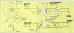
“Banana” (excessive bending) terminals: One of the most descriptive crimping problems is known as a “banana” crimp, because the crimped terminal takes on a banana shape (Fig. 4). This makes it difficult to insert the terminal into the housing and may cause terminal butting. The problem is easy to solve by adjusting the position of the hold-down pin on the crimp press. This small pin is located in the crimp press and contacts the terminal in the mating section while the crimp sections are being crimped onto the wire. During crimping, a significant amount of metal on one end of the terminal (in the crimp section) moves. These high forces tend to force the front of the terminal upwards, unless it’s held down by the aptly named "hold-down” pin.
Crimp is too far forward: One of the more obvious crimping problems is when part of the transition section is damaged. The front end of the transition section has an upwardly protruding tab called a “terminal stop.” The stop’s function is to prevent the terminal from being inserted too deeply into the housing. If the stop is severely damaged, the terminal can actually be pushed all the way through the housing. The solution is relatively simple. The problem occurs when the terminal and carrier strip, which is the band or strip of metal the terminals are attached to when you receive them from the manufacturer, isn’t properly located with respect to the press. To solve this, loosen the baseplate of the interchangeable tooling and realign it to the press.
Undersized bellmouth: The correct size for a bellmouth is about twice the thickness of the terminal material (Fig. 5). For example, if the terminal is made from material that’s 0.008 in. thick, the bellmouth should be about 0.016 in. While a few thousands of an inch won’t materially affect the terminal's performance, if the bellmouth is missing or if it’s less than one material thickness, there’s a risk of cutting the wire strands. The fewer strands that remain, the lower the termination strength. To correct the problem, make sure the punch and anvil on the crimping equipment are properly aligned.
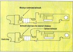
Oversized bellmouth: There’s also a problem if the bellmouth is oversized; this reduces the total contact area between the crimp section of the terminal and the wire. With decreased area in the wire-to terminal interface, wire pull-out force drops. If the crimp height is correct, then the likely cause is worn tooling.
Carrier cutoff is too long: The carrier strip is cut off the terminal during crimping . If the remaining cutoff is too long, problems can occur. The extra metal may protrude out of the rear of the connector when the terminal is inserted into the housing, causing the connector to arc between adjacent contacts when higher voltages are applied. If the carrier cutoff at the front of the terminal is too long, the extra length may interfere with connector mating and result in “terminal butting.” To correct the problem, the baseplate on the press should be adjusted so that the terminal is centered properly in the crimp press. Another indication that the terminal isn’t centered correctly is that the bellmouth is formed improperly. This occurs because the tooling for the bellmouth and the carrier cutoff are spatially related.
Bent locking tangs: Although bent locking tangs aren't necessarily the result of a poor crimping process, the connector can fail just the same. Locking tangs may be bent either in or out too far, which affects the terminal's ability to completely lock into the shelf in the housing designed for this purpose. The tangs may be damaged as the terminals are unwound from the reel if the friction wheel on the crimp press’s reel holder is too tight. Or, it can be caused by handling after the terminals are crimped onto the wires.
Typically, terminated wires are gathered into a bundle and inventoried or transported to another location in the plant. During the bundling, or as each terminated wire is removed from the bundle, the locking tangs may be bent. If the damage occurs at the crimping press, then the friction wheel must be adjusted so it’s just tight enough to keep the reel of terminals from being unwound by their own weight. If the problem occurs during bundling, smaller bundles or improved handling procedures need to be implemented.
While there are 13 problems that may be caused during crimping , there are just four simple rules that will help ensure success:
1. Choose the right connector for your application requirements.
2. Use the crimp tooling specified by the terminal manufacturer.
3. Properly adjust the crimp tooling and maintain it in good working order.
4. Periodically replace the parts that displace metal (conductor and insulation punches, anvils, and terminal cutters).
Visual Inspection of Crimped Terminals Poster (courtesy: Molex)
To keep up with Electronic Design’s latest automotive-related articles, please subscribe to our Automotive Electronics bi-weekly newsletter.
About the Author

Andy Turudic
Technology Editor, Electronic Design
Andy Turudic is a Technology Editor for Electronic Design Magazine, primarily covering Analog and Mixed-Signal circuits and devices and also is Editor of ED's bi-weekly Automotive Electronics newsletter.
He holds a Bachelor's in EE from the University of Windsor (Ontario Canada) and has been involved in electronics, semiconductors, and gearhead stuff, for a bit over a half century. Andy also enjoys teaching his engineerlings at Portland Community College as a part-time professor in their EET program.
"AndyT" brings his multidisciplinary engineering experience from companies that include National Semiconductor (now Texas Instruments), Altera (Intel), Agere, Zarlink, TriQuint,(now Qorvo), SW Bell (managing a research team at Bellcore, Bell Labs and Rockwell Science Center), Bell-Northern Research, and Northern Telecom.
After hours, when he's not working on the latest invention to add to his portfolio of 16 issued US patents, or on his DARPA Challenge drone entry, he's lending advice and experience to the electric vehicle conversion community from his mountain lair in the Pacific Northwet[sic].
AndyT's engineering blog, "Nonlinearities," publishes the 1st and 3rd Tuesday of each month. Andy's OpEd may appear at other times, with fair warning given by the Vu meter pic. His cartoon series, "Inventors", appears each week in Electronic Design Weekly.
Comment About the Article
To join the conversation, and become an exclusive member of Electronic Design, create an account today!

Leaders relevant to this article: