Why High-Current DC-DC Converters Still Run Hot and How Flat-Wire Inductors Help
Key Highlights
- Flat-wire inductors increase conductor packing density, reducing DCR and improving efficiency in high-current applications.
- Higher switching frequencies demand magnetic components that manage increased electrical and thermal stresses, which flat-wire designs help mitigate.
- Reducing winding and core losses through optimized winding geometry enhances thermal performance and system reliability.
- Magnetically shielded flat-wire inductors, like Bourns' ER26A series, support compact, high-current DC-DC converter designs.
- Winding geometry should be considered a key design variable to optimize efficiency, thermal management, and overall system performance.
On August 24, 2026 in Industrial, Power by Bourns
Inductors are simple, mysterious, essential, irreplaceable—and innovative
Modern DC-DC converters are expected to deliver more power from smaller spaces while operating at higher switching frequencies and current levels. Although advances in semiconductor technology have enabled significant improvements in switching efficiency and power density, thermal management remains a persistent challenge.
One reason is that the inductor, often viewed as a relatively simple passive component, can be a major contributor to converter losses, temperature rise, and overall size. Its electrical and magnetic characteristics affect efficiency, reliability, and system-level thermal performance. As a result, inductor winding geometry has become an increasingly important design consideration. With different approaches emerging, this blog explores how using flat-wire winding technology helps reduce losses and support more compact, high-current converter designs.
Modern Power Systems Need Better Magnetics
The trend toward higher-frequency switching continues to push the design of power converters. Higher switching frequencies can enable smaller magnetic and filtering components and therefore higher power density, but they also increase the importance of switching losses and frequency-dependent winding and core losses. At the same time, applications ranging from telecommunications infrastructure to industrial equipment and renewable-energy systems increasingly require higher output currents and improved efficiency.
Unlike semiconductor devices, however, inductors do not scale as easily. Even as switching devices become smaller and more efficient, magnetic components must still manage substantial electrical and thermal stresses. A high-current inductor must simultaneously handle DC current, ripple current, saturation limits, winding losses, core losses, and temperature rise.
As a result, the magnetic component often becomes a limiting factor in converter performance. Improvements in the switching stage alone cannot eliminate losses that originate in the inductor itself.
Causes of Thermal Stress
Heat generation in a high-current converter comes from multiple components and loss mechanisms. Within the inductor specifically, losses arise from both the winding and the magnetic core, and several of these mechanisms become more important as current and switching frequency increase. The most obvious contributor is DC conduction loss caused by winding resistance. Because power dissipation follows the familiar relationship P = I²R, even a small amount of DC resistance (DCR) can generate significant heat at high current levels. An inductor carrying tens or hundreds of amperes may dissipate substantial power from only a few milliohms (mΩ) of resistance. As current increases, these losses rise with the square of the current, making low DCR a critical design objective.
However, DCR is only part of the story. Additional losses include frequency-dependent AC winding losses caused by skin and proximity effects, including eddy currents driven by fringing and leakage magnetic fields, as well as losses within the magnetic core itself. Their magnitude depends on factors including switching frequency, current waveform, conductor geometry, magnetic-field distribution, gap geometry, core material, and flux-density swing.
Viewed from this perspective, converter heat is fundamentally an electrical-loss problem before it becomes a thermal-management problem. Reducing the mechanisms that generate loss is often more effective than attempting to remove the resulting heat after it has already been produced.
Flat-Wire Inductors Help Address Key Efficiency Challenges
One approach to reducing winding-related losses is to replace conventional round wire with flat wire.
Traditional round-wire windings leave unused space between adjacent conductors. Flat-wire windings can use the available winding window more efficiently, which increases conductor-packing density and improves utilization of the available core space (Figure 1).
Figure 1: Use of flat wire rather than round wire offers higher conductor-packing density in the available core space, bringing multiple performance benefits. (Source: Bourns)
By improving copper utilization within the available winding window, flat-wire construction can allow more conductor cross-sectional area or a more compact winding geometry for a given design, helping reduce DCR and the associated conduction loss (I²R). The benefits become especially noticeable in high-current applications because conduction loss scales with I², so even small reductions in resistance can produce meaningful efficiency and thermal gains. Lower resistance can support higher thermal current capability within a given package size, provided the design also meets saturation, temperature-rise, printed circuit board (PCB) layout, and cooling requirements.
Flat-wire construction can also provide advantages beyond lower DCR when the winding geometry is appropriately optimized. In some helical flat-wire designs, electromagnetic modeling has shown lower frequency-dependent AC winding resistance than comparable solid round-wire implementations. That said, flat wire is not a universal solution. AC resistance, eddy-current losses, magnetic field distribution, and gap design still influence overall performance. The interaction between conductor geometry, core material, winding arrangement, and operating frequency remains important. Effective inductor design still requires balancing multiple electrical, magnetic, and thermal factors.
Thermal and electromagnetic considerations also extend beyond the winding. Magnetically shielded constructions can help reduce stray magnetic-field coupling in dense converter layouts, although electromagnetic interference (EMI) performance ultimately depends on the complete design, including PCB layout, grounding strategy, switching-current loops, and nearby components.
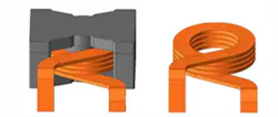
A practical example is the ER26A series of high-current inductors from Bourns. These devices use a helical flat-wire winding structure combined with a magnetically shielded design and high-temperature ferrite core (Figure 2). The series is intended for compact DC-DC converter applications requiring low DCR, high-current capability, and high saturation-current performance.
Figure 2: The Bourns ER26A high-current inductor uses flat helical windings to provide the necessary DC-DC converter inductance values in a small, high-current package. (Source: Bourns)
Conclusion
In high-current DC-DC converters, inductor losses are not limited to DC winding resistance. Frequency-dependent AC winding loss, core loss, fringing-field effects, and system-level thermal constraints can all contribute to temperature rise. As power density and operating currents increase, these effects can become limiting factors in converter efficiency, current capability, and reliability.
Flat-wire inductors help address several of these challenges by improving winding-window utilization, reducing DCR, lowering associated conduction losses, and supporting high-current operation in compact form factors. While they do not eliminate every loss mechanism, they provide designers with another tool for improving converter efficiency and thermal performance.
For this reason, winding geometry should be treated as a core design variable, not merely a packaging detail.
Author
Bill Schweber is a contributing writer for Mouser Electronics and an electronics engineer who has written three textbooks on electronic communications systems, as well as hundreds of technical articles, opinion columns, and product features. In past roles, he worked as a technical web-site manager for multiple topic-specific sites for EE Times, as well as both the Executive Editor and Analog Editor at EDN. At Analog Devices, Inc. (a leading vendor of analog and mixed-signal ICs), Bill was in marketing communications (public relations); as a result, he has been on both sides of the technical PR function, presenting company products, stories, and messages to the media and also as the recipient of these. Prior to the MarCom role at Analog, Bill was associate editor of their respected technical journal, and also worked in their product marketing and applications engineering groups. Before those roles, Bill was at Instron Corp., doing hands-on analog- and power-circuit design and systems integration for materials-testing machine controls. He has an MSEE (Univ. of Mass) and BSEE (Columbia Univ.), is a Registered Professional Engineer, and holds an Advanced Class amateur radio license. Bill has also planned, written, and presented on-line courses on a variety of engineering topics, including MOSFET basics, ADC selection, and driving LEDs.
About the Author
Bill Schweber
Bill Schweber is a contributing writer for Mouser Electronics and an electronics engineer who has written three textbooks on electronic communications systems, as well as hundreds of technical articles, opinion columns, and product features. In past roles, he worked as a technical web-site manager for multiple topic-specific sites for EE Times, as well as both the Executive Editor and Analog Editor at EDN. At Analog Devices, Inc. (a leading vendor of analog and mixed-signal ICs), Bill was in marketing communications (public relations); as a result, he has been on both sides of the technical PR function, presenting company products, stories, and messages to the media and also as the recipient of these. Prior to the MarCom role at Analog, Bill was associate editor of their respected technical journal, and also worked in their product marketing and applications engineering groups. Before those roles, Bill was at Instron Corp., doing hands-on analog- and power-circuit design and systems integration for materials-testing machine controls. He has an MSEE (Univ. of Mass) and BSEE (Columbia Univ.), is a Registered Professional Engineer, and holds an Advanced Class amateur radio license. Bill has also planned, written, and presented on-line courses on a variety of engineering topics, including MOSFET basics, ADC selection, and driving LEDs.
Comment About the Article
To join the conversation, and become an exclusive member of Electronic Design, create an account today!
 Leaders Logo
Leaders relevant to this article: