The All-Seeing Eye Takes to the Road: Vision Systems for ADAS
This file type includes high-resolution graphics and schematics when applicable.
Advanced driver assistance systems (ADAS) encompass a broad range of electronic technologies that increase automotive safety and improve driving performance. Safety-related ADAS can help avoid collisions and accidents by alerting the driver to potential problems or even taking over control of the vehicle. Adaptive ADAS may automatically dim headlights to avoid glare, detect driver drowsiness, provide adaptive cruise control, automate braking, incorporate GPS information or traffic warnings, connect to smartphones, warn of other cars or pedestrians, keep the driver in the correct lane, or eliminate blind spots.
In many ADAS designs, the vision system is an important component. The first automotive use of a camera was to help in backing up: The backup camera lets the driver see directly behind the vehicle, a job that’s difficult to do using only mirrors.
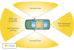
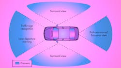
A typical installation includes a camera in each of the bumpers for front and rear views, and a camera in each door mirror for a side view. Each camera has a fisheye lens, and together they generate a complete image of what’s happening around the car. Data from the four cameras are sent to an applications processor that removes distortion caused by the lens, changes the apparent point of view, and merges the four images to generate a virtual bird’s-eye view of the automobile.The next step beyond this is the surround-view system (Fig. 1). Four vehicle-mounted cameras combine to form an “all-seeing eye.”
An ADAS vision system provides the driver with a three-dimensional view of the vehicle, but it’s capable of doing much more than that. For example, object-detection algorithms can provide collision warnings for several kinds of obstacles, such as other vehicles, pedestrians, or pillars; they also are able to measure the size of a possible parking slot. Furthermore, the image data can be used to alert the driver to pedestrians passing the car as it’s reversing.
An ADAS system typically consists of four camera modules and a central electronic control unit (ECU) that processes and combines the camera data. Let’s take a closer look at these modules.
ADAS Camera Module
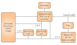
Figure 2 shows the block diagram of a compact 1.3-Mpixel camera module for automotive applications. The main components are a CMOS imager, a serializer, a filter, and a power-conversion block. The CMOS imager generates data that represents the image: its parallel output drives a serializer that converts the video data, including horizontal and vertical sync signals, to a unified high-speed serial stream that travels over a single coax cable to a deserializer located in the centralized electronic control unit (ECU). The deserializer processes the data streams from all four ADAS cameras and sends them downstream for further processing.
The coax cable also carries a separate low-latency bidirectional control channel that transmits imager control and configuration information from the system microcontroller via an I2C port. This control channel is independent of the video data stream.
Imager: OV10640
The OV10640 megapixel color imager from OmniVision is a 1/2.56-in. optical-format, 1280×1080 single-chip camera for automotive machine-vision applications. It can record highly detailed, full-resolution, 1.3-Mpixel images and video at 60 frames per second (fps). The sensor uses split-pixel HDR technology, in which the scene information is sampled simultaneously (rather than sequentially) for superior image quality in a 12-bit raw DVP output. The OV10640 can be configured using an I2C connection to Omnivision’s serial camera control bus (SCCB).
Serializer: DS90UB913A
A serializer that combines a 12-bit video with a bidirectional control signal into one coax or twisted-pair can greatly reduce system complexity, cost, and cabling requirements.
The DS90UB913A serializer includes an FPD-Link III interface FPD-Link III (flat-panel display link III), an interface used to transport point-to-point video in many automotive applications. It includes both a high-speed forward channel and a bidirectional control channel, and uses differential signaling to provide a range of up to 15 meters.
POC Filter
The coaxial cable also delivers dc power to the camera module, an arrangement known as Power Over Coax (POC). The video channel and the control channel occupy different spaces in the frequency domain. In this design, the control channel occupies the space from about 1 MHz to about 5 MHz. The video channel occupies the frequency spectrum from about 70 MHz to about 700 MHz. Adding power to the cable must be accomplished without interfering with either of these two bands.
To combine both power and data into a single cable, a POC filter is inserted into the signal path that splits the signal into two branches (Fig. 3). One branch passes both the back channel and forward channel, but blocks the dc; the other branch performs the opposite function, letting through the dc and blocking the higher-frequency components.
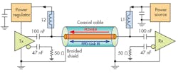
A simple capacitor can separate the ac signals from the dc power. A 100-nF capacitor, for example, has very low impedance over the 1- to 700-MHz range. It is readily available and inexpensive. Because the parasitic inductance of a 0.1-µF, 0603 capacitor is around 1 nH, it doesn’t affect the band of interest.
Designing the other branch is more complicated. Since the communication medium is a controlled-impedance 50-Ω transmission line, the impedance of the low-pass circuit must be at least 20X larger than this (i.e., 1000 Ω) over the 1- to 700-MHz bandwidth.
An ideal inductor would fit the bill perfectly, but not surprisingly, these are hard to find. A real-world inductor has both resistance and parasitic capacitance—it’s a resonant circuit and is modeled as a series resistance and inductance in parallel with a capacitance. At low frequencies, the impedance of an inductor is essentially that of the wire’s resistance. It then increases with frequency up to a peak value at its self-resonant frequency. At higher frequencies, the parasitic capacitance becomes increasingly dominant, which decreases the impedance.
The power consumption of the camera module components also affects the design. For a given power consumption, increasing the operating voltage allows designers to use an inductor with lower saturation current, which takes up less space. To keep the filter’s impedance above 1 kΩ over the whole bandwidth, the POC filter requires a pair of inductors in series. The full design procedure is described in TI Application Report SNLA224.
Overview of the ECU
The four camera modules are connected to an ECU hub, which combines the data streams and provides system power. Fig. 4 shows the ECU block diagram as part of an entire ADAS reference design, which includes an interface to an additional evaluation module (EVM) for the downstream processor.
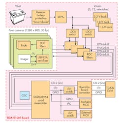
The primary components are:
• POC filters: The POC filters on the ECU have two functions: to supply a clean dc supply to the switching regulators on the camera modules; and to protect the FPD-Link III communication channels from noise coupled in from other system components, particularly the switching frequencies from those same regulators. As can be seen in Fig. 3, the ECU filter is similar to the camera-module POC filter. The filter design is discussed in the ADAS reference design user guide.
• Deserializer: The DS90UB964 is a four-port deserializer that receives the FPD-Link III data and aggregates it into dual Mobile Industry Processor Interface (MIPI) Camera Serial Interface (CSI)-2 output ports. The DS90UB964 can use the second port to provide additional bandwidth or as a port replicator. In port-replication mode, a machine-vision algorithm is able to process one stream for a real-time task such as object recognition, while the other stream can be sent to a data-logging device for future analysis.
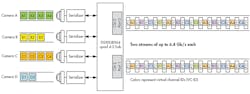
Although the camera modules may be identical in an ADAS vision system, the deserializer can fuse data from multiple sensors of different types, resolutions, or speeds (Fig. 5). Each CSI-2 port can provide the aggregate data at a rate of up to 6.4 Gb/s, and reverts to a low-power mode when not in use.
• Image signal processor: Two OV490 image signal processors (ISPs) process the deserialized data streams from the four OV10640 image sensors. Each ISP can handle two image sensors. For each OV10640, the OV490 generates a pair of simultaneous outputs: RAW data for machine-vision downstream processing; or fully-processed YUV or RGB data for display-based applications. The device uses a 32-bit RISC processor to facilitate high-quality image capture and video streaming.
• Power management: Since this is an automotive design, the nominal input voltage is 12 V. The camera supply is configurable from 5 to 14 V. Since this is both above and below the input voltage, a TPS55340 converter is used in a single-ended primary-inductor converter SEPIC configuration. The SEPIC configuration can operate as both a buck and boost converter. The converter’s switching frequency is 2.5 MHz, minimizing the potential for AM band interference.
In addition to the TPS55340, several buck converters generate the required ECU power-supply voltages.
• Applications processor: The EVM includes a connector to interface with a separate application processor board. TI’s TDAx system-on-chip (SoC), for example, is a scalable family of devices designed to meet ADAS and other vision-system requirements. TDAx family members include devices with both fixed and floating-point digital signal processors (DSPs), a range of ARM Cortex cores, and embedded-vision-engine (EVE) coprocessors that are optimized for vision processing.
There’s also a complete set of development tools for the ARM, DSP, and EVE, including C compilers, a DSP assembly optimizer, and a debugging interface.
Conclusion
ADAS systems will assume increasing importance in coming years, with the global ADAS market growing at a CAGR of 23% and expected to reach $60B by 2020. Vision systems will make up a key segment within that market.
An ADAS vision system requires a mix of components that perform imaging, high-speed serial communications, and downstream processing functions. Texas Instruments’ product portfolio and applications assistance help simplify the design of this complex system.

About the Author
Paul Pickering
Paul Pickering has over 35 years of engineering and marketing experience, including stints in automotive electronics, precision analog, power semiconductors, flight simulation and robotics. Originally from the North-East of England, he has lived and worked in Europe, the US, and Japan. He has a B.Sc. (Hons) in Physics & Electronics from Royal Holloway College, University of London, and has done graduate work at Tulsa University. In his spare time, he plays and teaches the guitar in the Phoenix, Ariz. area
Comment About the Article
To join the conversation, and become an exclusive member of Electronic Design, create an account today!

Leaders relevant to this article: