A Practitioner’s Guide To Critical Software Certification
Download this article in .PDF format
This file type includes high resolution graphics and schematics.
Software plays an increasingly important role in the development of many critical projects, whether in avionics, nuclear power stations, cars, trains, or medical devices. When the cost of a software failure is great, it becomes more important to ensure that the software functions as expected and is safe.
In some cases, the cost may be financial, such as the monetary value associated with a product recall, replacement, or repair. In other cases, the cost may be a risk of severe injury or death.
Designers can verify that their software is correct and safe by certifying it to a specific standard. Fortunately, best practices are available to help designers achieve critical software certification.
Safety-Critical Standards
There are two principal safety-critical standards or guidelines: avionics and industrial. The DO-178B guidelines, which have been in place since the early 1990s, have been very successful in bringing avionics to a stellar level of software safety. DO-178B accounts for new technologies such as model driven development.
In the industrial realm, IEC 61508 was updated in 2010. Other industries have realized the need to certify the software included in their products. In fact, IEC 61508 has been used as the foundation for several domain-specific standards:
- Automotive: ISO 26262
- Medical: IEC 62304
- Railway: CENELEC EN 50128
- Nuclear: IEC 61513
- Process: IEC 61511
Each standard defines safety integrity levels (SILs) that depend on the severity of the consequences of failure. The safety level must be examined and determined for each software component. These allocated safety levels ultimately determine the level of rigor that must be applied to the development process for the associated software.
The lower a SIL, the less critical the application and consequently less stringent development and verification practices are required. As the SIL increases, so does the need to reduce risk and more strictly verify the product.
Definitions vary by standard. IEC 61508 defines a range from SIL 1 to SIL 4, where SIL 1 is the lowest level of safety and SIL 4 is the highest. Each level reduces the risk roughly by a factor of 10. SIL 3 is the highest level that can be attained by a single software component. SIL 4 requires hardware redundancy of SIL 3 components. In IEC 62304, the safety levels go from the lowest Class A (no injury or damage to health possible) to the highest Class C (death or serious injury possible).
Each standard outlines a number of objectives, sometimes called requirements, that must be met to pass certification. These objectives concern not just the design phase, but also the verification and validation of the design. Depending on the SIL, all or a subset of these objectives must be met.
Two types of inputs may be required to satisfy an objective. Assets are principally created during the design phase (e.g., system requirements, software requirements, risk and safety documents, and source code) and need to be available prior to accomplishing the objective. Artifacts are principally created during the verification and validation phases (e.g., test cases, code coverage reports, and code analysis reports) and are produced to satisfy the objective.
Notably, assets and artifacts can be almost anything, such as PDF files, Word documents, HTML reports, source code, or test cases. As assets and artifacts are completed, they are linked with the appropriate objective, creating a map from the objective to the various evidence.
Figure 1 shows an example of two such objectives and their associated assets and artifacts. We can see that that the objective 7.2.2 has been partially fulfilled. The output from this objective has been used as an input to the following objective 7.3.2.
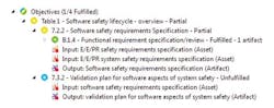
1. Objectives outline the steps needed to meet certification. Input assets and output artifacts provide the proof of an objective’s completion.
One of the key points in critical software certification is requirements traceability. This refers to linking system requirements to software requirements, from the software requirements to design requirements and then to source code and the associated test cases.
Tracing requirements is the best way to ensure that the final system does exactly what is specified by the initial requirements—nothing more, nothing less. It confirms that there is no extra “dead” code and no missing features. Requirements traceability provides the evidence that all system requirements have been fulfilled.
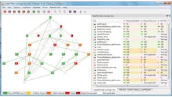
The key deliverable of this activity is a requirements traceability matrix (RTM). Figure 2 shows an example of a graphical representation of an RTM, where the traceability is clearly visualized from the high-level requirement on the left to the verification tasks and mapped source code on the right.
2. The requirements traceability matrix (RTM) covers everything from high-level requirements to source code and verification tasks.
Sophisticated requirements mapping enables the developer to quickly identify what code and tests prove a requirement is fulfilled. It also permits the developer to assess the upstream and downstream impact that changes have throughout the RTM. Such feedback is essential to best practices for software certification.
Requirements traceability in particular benefits from the use of tools. Managing with traditional manual methods, such as spreadsheets, demands resource-intensive labor that is often error prone. Tools that automatically track the link between requirements, models, code, and tests simplify the process and ensure that all certification documentation is also tracked as the project progresses through development. The more sophisticated tools on the market provide complete end-to-end traceability from initial design right through to source code and associated test outcomes.
Coding Standards And Complexity
The Pareto principle applies to software development—generally 80% of software defects are caused by 20% of the language constructs. Clearly, avoiding those constructs is the best way to avoid these defects in your code. By limiting the use of the language to a safe subset, you can avoid a significant proportion of potential problems. The MISRA-C: 2004 standard defines a subset of the C programming language that has been deemed safe.
Additionally, some standards suggest the use of style guides in addition to the language subset, such as the placement of brackets, use of indentation, and interdiction of the tab character. Coding standards such as the JSF++ AV or Netrino standards combine the use of a language subset with style guidelines to ensure that code written by different coders looks the same in any editor and is therefore more easily understood. Additional benefits may then carry forward to testing activities and future code maintenance.
It might be impossible to avoid all complexity, but it is possible to avoid unnecessary complexity. Metrics such as cyclomatic complexity and knots can be calculated to determine the complexity of a function and show whether or not the function has been written in a structured manner. When combined with structured programming verification (SPV) techniques, these metrics may be further refined to provide measures of essential cyclomatic complexity and essential knots—both indices of whether code may have unnecessary complexity.
Many guidelines, such as IEC 61508, recommend the measurement of software complexity metrics. One way to visualize complexity is with a flow graph. Figure 3 shows how a function can be represented graphically, where each circle represents a block of continuous statements and each line between the circles represents the control-flow branches. Such graphical representations are very useful for providing a quick overview of a function’s complexity.
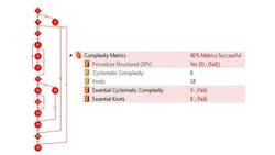
3. The complexity of code can be expressed visually in a flowgraph or in reports to enforce structure-based coding practices.
Figure 3 also shows how the metrics could be reported. In this specific case, if they are outside of the defined lower and upper limits, then they are reported as failed. Hence, such metrics may be actively used to enforce structure-based coding practices. When combined with language subsets and style guides, complexity metrics help code to be more readily understood, tested, and maintained.
Control flow analysis is performed both on the program calling hierarchy and on the individual procedures. The rules of structured programming are applied and defects reported. Figure 4 depicts how a call graph documents the control flow analysis, showing exactly which functions are invoked by which others.

4. A callgraph represents the calling hierarchy of a system. It can easily document how functions interact with one another.
Testing Challenges
Irrespective of SIL level, black box and functional testing must be included, as well as dynamic analysis. Of course, this testing needs to be performed against the requirements with test outcomes being fed back via the requirements traceability techniques.
Unit tests can be executed on the host or the target depending on the internal process and SIL defined by your standard. Doing so ensures that each unit under test functions as expected. When unit testing, any missing functions need to be stubbed and a harness created to support the execution of the tests.
Manually creating stubs and harnesses and downloading and executing tests on the target can be very tedious tasks. But with the right unit testing tool, all these tasks can be seamlessly automated, easily taking care of the mundane errors that are so often missed and can lead to problems.
Structural Coverage Analysis
The problem with testing is knowing when you have done enough, and this isn’t as easy as it seems. According to industry consultant Jack Ganssle, “Studies confirm that, without the use of code coverage analysis, testing typically exercises only 50% of the code. Given typical bug rates, that means 100k lines of code in a program will ship with 2500 to 5000 bugs. These bugs lead to many systems failures.”
Structural coverage analysis (SCA) provides a solution. SCA measures the code while it is executed during testing, providing a code coverage metric that highlights portions of code that have not been executed. The code coverage data can help developers identify deficient or bad test cases or unexecuted “dead” code. When combined with the requirement traceability techniques, SCA can indicate when a requirement has been fully implemented and tested or highlight deficiencies in requirements or implementation.
The required types of coverage depend on the SIL level to be attained. From least to most rigorous, coverage can be attained for:
- Statement
- Branch/decision
- MC/DC (modified condition/decision coverage)
- LCSAJ (linear code sequence and jump)
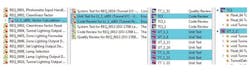
Figure 5 illustrates how the code coverage information can be reported. As with other metric reporting, with the right tools and techniques in place, high levels of automation can be achieved.
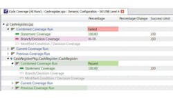
5. Code coverage metrics can identify unexecuted “dead” code or highlight missing test cases.
Pass/fail criteria relative to the required SIL can be determined and reported so it is immediately clear whether or not coverage requirements have been satisfied. Deficiencies in structural coverage may indicate the need for further requirements-based testing or additional, unnecessary functionality that should be removed from the software.
When source code is compiled, it often isn’t possible to directly trace from the code to the generated object code due to factors such as the coding constructs used, compiler/target configuration, or compiler optimizations. At the highest levels of criticality, it becomes necessary to verify that these differences do not have an adverse effect on the functionality of the software and that structural code coverage be attained on the object code. This level of coverage analysis demonstrates that all assembly instructions have been executed and tested fully.
Fitting Tools Into The Process
The best practice techniques associated with the certification of safety-critical software are extensive and varied, depending on the SIL. Clearly, the use of tools provides the opportunity to apply the necessary techniques with uniformity of rigour, as demanded by the allocated SIL, with the additional benefit of significant efficiency gains through automation.
Ideally, tools need to be deployed from the beginning of the development process to gain maximum benefit. In choosing such tools, it is important to ensure that they support the widest set of techniques to satisfy all SIL requirements and that they may be qualified in the context of their use within the project.
Certification of safety-critical software is neither fast nor easy, but it is essential. Although tools add to the upfront investment of the development project, the savings in errors avoided, enhanced clarity and maintainability of code, documented certification process, and reduced time-to-market result in reductions in cost over the system lifetime that significantly outweigh the purchase price of the tools.
Industries such as avionics that have spearheaded certification efforts demonstrate that the final outcome is worth the effort. With the right tools and the guidance of certification standards, it is possible to develop code that not only functions correctly but also reduces the financial and physical risks associated with critical applications.
References
1. European Organisation for Civil Aviation Equipment, Software Considerations in Airborne Systems and Equipment Certification (ED‑12B/DO-178B), EUROCAE, 17 rue Hamelin, F-75783 Paris Cedex 16, France, 1992. Available at http://www.eurocae.org.
2. International Electrotechnical Commission, Functional Safety of Electrical/Electronic/Programmable Electronic Safety-related Systems (IEC 61508), International Electrotechnical Commission, 3 rue de Varembé, Geneva, Switzerland, 1998. Available at http://www.iec.org.ch.
Download this article in .PDF format
This file type includes high resolution graphics and schematics.
About the Author

Jared Fry
Jared Fryis a field application engineer for LDRA Ltd. He graduated from Western New Mexico University with degrees in mathematics and computer science. His career began in the defense industry with Lockheed Martin as a software engineer working on various projects including missile and radar systems, training simulations, and software testing. With LDRA he leverages these experiences as a consultant, assisting clients throughout the development process to produce a quality and certifiable product.

Shan Bhattacharya
Shan Bhattacharyais a field application engineer for LDRA. He graduated from Cameron University and began his career in factory automation and robotics. He continued his career with various defense contractors including Lockheed Martin, where he served as a lead engineer and finished his time as a deputy IPT lead. He has been with LDRA since 2007 and provides consultation for clients in various industries focusing on requirements management, software certifications, and development best practices.
Comment About the Article
To join the conversation, and become an exclusive member of Electronic Design, create an account today!

Leaders relevant to this article: