What’s the Difference Between IO-Link and Discrete Sensor Interfaces?
Connecting sensors and actuators to a network can be a challenge when dealing with discrete analog connections. The input connections are usually supported by analog-to-digital converters (ADCs), and digital-to-analog converters (DACs) are used for outputs. Digital binary sensors are more commonly used for machine automation, but lack any extra intelligence and diagnostics.
For analog sensors, part of the challenge is that the ADCs and DACs must be matched to the sensor or control devices. Likewise, the data used with these interfaces needs to be scaled accordingly. Many devices also require calibration.
IO link is targeted for machine automation with up to 20 meters in data communication link. The advantage for analog, i.e., 4-20mA, is for long-distance communication typically used for process automation. The disadvantage is the complexity leading to increased hardware and software design costs such as expensive shielded cabling.
Some of the key benefits of IO-Link are:
- Reduces maintenance and increased uptime
- Brings intelligence down to the sensor level
- Plug, play, and walk away
- Parameter settings can be downloaded from uC (no longer manual)
- Easy parameterization without down time associated with machine changeover
- Continuous diagnostics and monitoring
- Improved data logging and error detection
- Robust digital communication
- Reduces costs by making installation easier through the use of a standard sensor connector that allows direct binary sensor upgrades
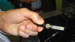
One alternative to discrete connections is to use an intelligent, point-to-point interface like IO-Link (Fig. 1). IO-Link is the common name for the IEC 61131-9 standard that is handled by a Technical Committee (TC6) and Working Group within PI (PROFIBUS & PROFINET International).
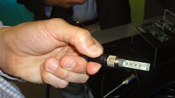
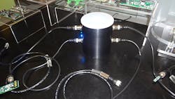
IO-Link is a three-wire (Fig. 2) that has a 24 V connection that supports up to 200 mA. A single-wire, half-duplex serial interface operates at 4.8, 38.4, or 230.4 kbaud. A five-wire IP65/67 connector is normally used with IO-Link devices. IO-Link products are available from a wide range of vendors, including Maxim Integrated (Fig. 3). An IO-Link master is often a gateway to a fieldbus and they control and service IO-Link devices. IO-Link masters normally have an M12 connector for each device (Fig. 4). Unshielded IO-Link cables can be up to 20 m in length.
An IO-Link master port communication signal can operate in one of four modes: IO-Link mode, DI mode, DQ mode, or deactivated. IO-Link mode uses the half-duplex serial interface supporting up to 32 bytes of process data. DI is a digital input mode and DQ is a digital output mode.
A master will initiate communication with a device. A device will support one of the standard communication rates and the master will determine which one it is. The master then exchanges configuration parameters from the device and then switches to cyclic exchanges of process data and values.
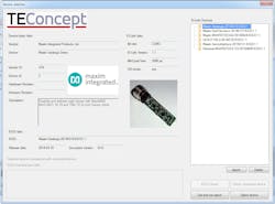
IO-Link specifies device profiles. This allows easy interchange of devices. The IO Device Description (IODD) provides a fixed, standard description of a device (Fig. 5). The IODD file contains:
- Communication properties
- Device parameters with value range and default value
- Identification, process, and diagnostic data
- Device data
- Text description
- Illustration of the device
- Logo of the manufacturer
IO-Link is designed to provide a standard, low-speed, intelligent interface to devices. Devices from different vendors with the same specifications should be interchangeable. At this point there are two types of devices on the market that are compatible with the 1.0 and 1.1 standard. Newer 1.1 masters support 1.0 and 1.1 devices.
About the Author
William G. Wong
Senior Content Director - Electronic Design and Microwaves & RF
I am Editor of Electronic Design focusing on embedded, software, and systems. As Senior Content Director, I also manage Microwaves & RF and I work with a great team of editors to provide engineers, programmers, developers and technical managers with interesting and useful articles and videos on a regular basis. Check out our free newsletters to see the latest content.
You can send press releases for new products for possible coverage on the website. I am also interested in receiving contributed articles for publishing on our website. Use our template and send to me along with a signed release form.
Check out my blog, AltEmbedded on Electronic Design, as well as his latest articles on this site that are listed below.
You can visit my social media via these links:
- AltEmbedded on Electronic Design
- Bill Wong on Facebook
- @AltEmbedded on Twitter
- Bill Wong on LinkedIn
I earned a Bachelor of Electrical Engineering at the Georgia Institute of Technology and a Masters in Computer Science from Rutgers University. I still do a bit of programming using everything from C and C++ to Rust and Ada/SPARK. I do a bit of PHP programming for Drupal websites. I have posted a few Drupal modules.
I still get a hand on software and electronic hardware. Some of this can be found on our Kit Close-Up video series. You can also see me on many of our TechXchange Talk videos. I am interested in a range of projects from robotics to artificial intelligence.


