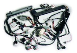
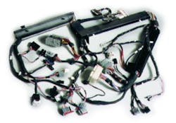
Interestingly, though, certain items in cable technology haven’t changed very much, and many small, simple cables still are used. However, there also are the 20,000-wire assemblies with loads of passive components. These present real challenges for today’s test-equipment manufacturer.
Throughput Rates and Costs
Personnel cost is an item of major interest in cable testing. How long does it take to connect, test, and disconnect a good cable? How much time is required to locate the fault in a defective cable? What proficiency level is required for each of these tasks? Just what is the throughput rate and cost of test?
Throughput involves much more than test speed. You must consider the time from the initial setup until the product passes all tests. You need special tooling to set up the assembly. The test system should provide accurate error information, diagnosing each failing condition quickly and showing the operator graphically how to locate and fix the problem.
Test-system manufacturers are quick to point out that actual test time is not a bottleneck. Most cables in high-production areas have less than 500 points, so the actual test time is quite short compared to the hookup, removal, and processing cycles.
“Three issues are critical to achieve the optimum throughput,” according to Mike Mathews, managing director at Electrotest. “First, efficiently adapting each cable under test to its fixture can greatly enhance the operation. Second, a system must be adaptable to product variations. In some applications, similar cables can incorporate different options. Software should respond to this uniqueness without delaying the test sequence.
“Finally, when a pass/fail decision is made, the tester should generate a report and a suitable label. The method of marking a failure must be foolproof to avoid mixing bad cables with good ones,” he explained.
Most manufacturers have developed innovative ways to speed up the test of cables and harnesses. For example, the CAMI PC-based CableEye® Tester includes a macro to improve throughput, reduce the probability of operator error, and ensure consistency. The operator simply attaches the cable and pushes one button. The automated sequence is defined by the test engineer and typically calls for visible and audible pass/fail indicators and prints the test report and a label. The system can be triggered by automatic assembly equipment and initiate a switch closure when a test is completed.
Cirris also has several techniques for increasing test rates, including the one-button starter, fast scan rates, shorts detection, high-speed hipot testing, and an integrated build-test capability. The Touch 1™ checks a 128-conductor cable for shorts and miswires in 0.25 s, and the hipot test takes 0.5 s.
In high-volume manufacturing, many companies use up to 30 carousels when assembling complex cables. Each operator at one of these assembly points builds one part of the product.
Dynalab recommends putting a tester at every position so that any locally produced errors can be identified and corrected on the spot. At the final carousel station, a label must be printed to validate the passing condition of the overall cable. Since putting a label printer at each operator position would be expensive and occupy valuable space, the company developed an infrared (IR) transmitter for each test point and an IR receiver at the label printer to serve the need at minimum cost.
You Can’t Wait on the PC
Typically, a cable tester incorporates or interfaces with a PC. However, the value of the PC is not so much its control but rather its capability to collect data, analyze test results, create customized reports, and print labels.
“The PC shouldn’t be in the real-time loop,” Mr. Mathews of Electrotest suggested, “because it slows the process by requiring a manual input and a specialized operator. A programmed controller generally is faster and more reliable. However, reporting and error analysis depend on the PC. Operating at a higher level in the test sequence, it can identify trends and nonrandom failures for the test engineer or manager to resolve.”
Windows-based software offers an advantage in cable testing systems because of its capability to use a vast array of applications programs. The executive creates a database with all the measurements so you can perform analysis using the optimum tool. The test results can be read by spreadsheet programs such as Excel, database programs like Access and Oracle, or report-generation routines such as Crystal Reports.
“Error analysis offers the greatest opportunity to ship good products quickly,” according to Karl Sweers, technical marketing director at DIT-MCO. “Wiring diagrams, pictures, and instructions help the operator pinpoint each failure. This can shave hours off the test cycle for a large and complex product. The executive is networked to allow test engineers to monitor results remotely, offer guidance, and help resolve problems. They even can take control of the system remotely to perform diagnostic testing.”
Testing More Than Wires
Ideally, a tester should recognize and handle the passive components that are an integral part of the more complex cables. There is a straightforward way to identify the simplest of these components. Set a conduction threshold, typically 2 W, and an isolation threshold, probably 1 MW. Measurements below the conduction point are closed, those above the isolation resistance are unconnected, and all points between the numbers are resistors. Resistance in one direction but not the other indicates a diode. The versatile tester also can test capacitors and create the test program, autolearning the components from a good cable.
Some manufacturers have added a new dimension to their cable testers with functional test buses. Electrotest’s Electro Emulation System can include instruments and power supplies to conduct a functional test of a wired assembly, and the DIT-MCO Multiple Bus Analyzer is a cable/harness tester that also exercises electronic assemblies. It provides 10 buses that connect any instrument to any point in the product.
Cable test companies have success stories to share. For example, “One of our customers, Pulsecom, makes a backplane with resistors, capacitors, and diodes,” noted Mr. Mathews of Electrotest. “The company must verify the values of these components, check the insulation resistance to ensure that power and ground circuits are isolated, and insert paddle cards into the assembly. We provided a turnkey system that accomplishes all of this with an order-of-magnitude reduction in test time. Also, our system can be reconfigured for a different backplane design in just a few minutes.”
Simple Cables—Complex Cables
Some cables and harnesses are relatively simple. There aren’t many wires, and the passive components are easy to detect and evaluate. However, there are the other extremes—cables with thousands of test points and a wide assortment of parts. How do test-equipment suppliers recommend handling each size?
Cirris pointed to its easy-wire™ components that enable you to configure a large or small system as required. The company recommends that you buy just what is needed, knowing that modules can be added later if the requirements expand.
Electrotest explained that the number of switching points in each of its products expands by adding modules. However, a low-voltage tester can’t be upgraded to test at 2,000 VDC. Expandability is a function of the test points, the stimulus voltage, and the instruments that are required. To save money over the long haul, the company recommends that you identify the likely expansion path before buying a system.
One manufacturer had the unique opportunity to help one of its suppliers with a tester for a relatively simple cable. “The supplier,” according to Greg VonRehder, product manager at B+K Precision, “makes harnesses for one of our products but was unable to test them quickly and accurately. We were intimately familiar with the product, so we sold them a custom test harness with the 205 Universal Cable Tester. Now our harnesses are tested and shipped to us on time, the quality is established through better tests, and the supplier’s labor costs are lower.”
More Success Stories
Each test-equipment manufacturer has stories about special testing problems solved with their systems. These are reminders that the cable-testing technology rewards innovative solutions.
For example, “One of our customers, ITW Linx, manufactures I/O protection modules, each a 2×1 multiplexer with 32 inputs,” said Brent Stringham, the director of sales and marketing at Cirris Systems. “Voltage suppressors on the input pins handle differential- and common-mode transients, and suppressors on the output pins handle only differential-mode transients. Skilled technicians and an array of equipment for product testing were used, and it was a slow process.
“The ITW Linx plant manager saw our automated cable/harness tester in another test setup,” he continued. “Impressed by the easy setup and high-speed testing, he envisioned using a similar system to test his modules. We incorporated our Touch 1 System and reduced the testing time from 30 minutes to 2 minutes. Furthermore, the test is so simple that a production worker can be trained in just a few minutes.”
High-resistance leakage, once a very difficult defect to detect on many testers, isn’t nearly as elusive for newer models because the operator can set the upper and lower test limits. For DIT-MCO, this feature proved itself very useful when a relatively new cable was returned to a telcom company because it did not work properly in a field installation. An old tester showed this cable to be good.
“The cable was moved to our recently installed tester,” Mr. Sweers of DIT-MCO said. “Because resistance limits were judiciously set on the system, on the first pass it detected high-resistance leakage on one of the circuits. The problem, caused when an arc left a carbon trace, was repaired, and the equipment was returned to service in the field.”
A Cable-Tester’s Dream
Even with all the advancements of the past few years, manufacturers constantly are dreaming of innovative ways to expand the function and increase the throughput of cable testers. Here is how Mr. Mathews of Electrotest envisions the ideal cable test world: “The system could get its instructions automatically from a network server. It starts the test when the cable is attached and reports errors to the network for processing and analysis.
“The test operator’s duties would be limited to connecting and disconnecting the cables. Repairs could be made on a separate networked tester where a more highly trained technician tests and repairs the product. Scanned images would show the location of errors.”
Will this happen? Of course it will. This year’s new cable testers were last year’s dreams, and today’s dreams will be tomorrow’s testers.
Return to EE Home Page
Published by EE-Evaluation Engineering
All contents © 2001 Nelson Publishing Inc.
No reprint, distribution, or reuse in any medium is permitted
without the express written consent of the publisher.
June 2001

