PXI-Gration Provides Solution for Obsolete Test Systems
When selecting hardware for the new tester, it is very important to choose a state-of-the-art platform that will guarantee many years of obsolescence-free operation. When selecting the software, simplify the migration process by choosing a platform that’s similar to the software package used to develop the obsolete tester.
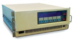
The PXI architecture offers state-of-the-art technology combined with simple migration or PXI-gration from some older systems to new technology. One such system is the Summation SigmaSeries.
Fighting Obsolescence With PXI-Gration
At first, support was available for the SigmaSeries products, and replacement cards could be obtained on the used-equipment market. Today, this no longer is true, and SigmaSeries users must find a solution to the obsolescence problem.
While most Summation cards were straightforward test and measurement instruments such as DMM, counter, arbitrary waveform generator, and switching cards, a few focused on digital and microprocessor test applications. These included the EMX ROM Emulator, the high-speed DSR Digital I/O Cards, and the static DIL, DOL, and DPO I/O Cards. The SigmaSeries chassis also had a sophisticated cross-trigger bus (CT.BUS) that supported intercard synchronization.
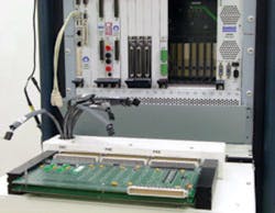
To overcome the obsolescence issues, we began providing customers a PXI-gration path from the now-obsolete Summation test product with the launch of the combination PXI 3U/6U product line. Many of the new products were based upon our existing GTXI and ISA bus-based products. Similar to when National Instruments launched its 3U offerings a few years earlier, we asked other test and measurement companies to develop complementary PXI products.
Several companies that manufactured ISA bus cards such as DMMs, universal time interval counters, and ROM emulators created 3U and 6U PXI versions of their products. Because of these and other company’s efforts, we began to migrate the SigmaSeries TestStations to PXI.
The SigmaSeries featured a number of buses dedicated to specific functions within the system, such as signal switching, and included a VME bus similar to VXI for computer communications. The TestStation’s TestFrame supported three buses:
- The high-accuracy bus (HA.BUS) is a low thermal offset, high-voltage analog bus consisting of two separate, guarded, floating four-wire buses. The four lines provide a four-wire resistance measurement capability and remote sensing. This bus is available at all module slots but not between the TestFrame card cages. If the expansion chassis required access to the HA.BUS, then specialized switching cards provided external access for routing the signals to the next chassis.
- The high-frequency bus (HF.BUS) consists of 10 single-ended unterminated lines each with a 50-W characteristic impedance. It is used primarily for routing high-frequency, low-voltage signals to measurement and stimulus modules such as the SigmaSeries universal counter (UCT10), the digitizer or waveform recorder (WFR10), and the function generator (FNG10). Since it is not carried between chassis, a specialized switching card provides access to the HF.BUS in its host chassis or TestFrame.
- The CT.BUS, the means to synchronize instruments within a chassis as well as externally, consists of seven lines (Figure 2). The CT.BUS signals allow modules to trigger or be triggered by an event occurring in another module. A CT.BUS extender card accomplished cross-tiggering between one chassis and the next. All CT.BUS signals were available in every card slot.
The PXI trigger bus closely resembles the SigmaSeries CT.BUS. We developed variations of existing digital I/O products to support the CT.BUS functions. The cross-trigger or PXI trigger buses are key to efficient, high-speed synchronization between test-system instruments.
The PXI-gration from the Summation TestFrame to a PXI chassis is possible because of the similarity between the two systems. The HA.BUS and the HF.BUS seldom were used in most SigmaSeries applications, and the PXI replacement system contains 6U PXI high-density switching cards to manage those buses. However, most Summation configurations did use the CT.BUS extensively which prompted us to address this bus in the PXI configuration using the PXI trigger buses.
The PXI-gration effort also studied the legacy SigmaSeries TestStation. We determined we could provide almost 100% compatibility with the existing fixtures. This helped to reduce costs and recapture the customers’ existing test-fixture investment.
PXI-gration supports the migration from existing hardware. Our ATEasy software product was enhanced to allow migration of the SigmaSeries TestCase test programs, a Windows-based form of BASIC similar to ATEasy.
The TestCase environment incorporates more than a version of BASIC for programming instruments. It also includes a test executive, a fault dictionary, and graphical tools for developing the setup and various configurations for the test-system resources.
ATEasy can directly import the TestCase files, including the DSR10 and other instrument files. This provided the means to migrate the existing test programs onto the PXI-based test system.
Taking the PXI Trigger Bus External
Migrating test programs and fixtures from the SigmaSeries to the PXI bus architecture was a challenge. Existing 6U PXI products were modified and released as new products to achieve this PXI-gration. For example, SigmaSeries PXI-gration required a PXI card that provides both access to and control of the PXI trigger bus.
The SigmaSeries had an optional expansion card to bridge the CT.BUS to the expansion chassis. Our GX5731, a 6U PXI high-density digital I/O card FPGA design, was modified to support this enhanced CT.BUS function. The new version provides external access to the PXI trigger bus for managing the bus.
The GX5731 also serves as a carrier for several piggyback or expansion cards. While many such expansion cards, including custom ones, are available for the GX5731, this particular application used several expansion cards to replace obsolete Summation digital instruments such as the SigmaSeries DIL10, DOL10, and DPO10.
There are a couple of reasons why separate access was provided to the PXI and cross-trigger buses. The PXI-gration of the existing test programs and fixtures required access to the CT.BUS for external instruments. The PXI trigger bus may similarly be required for future growth or new test-program development.
The GX5731 static digital I/O card provides locations for the addition of daughter cards for specific I/O functions. In the case of replacing obsolete SigmaSeries hardware, this card replaced three digital cards that all used the CT.BUS. The card must manage and configure access for these modules as well, meaning that the PXI trigger bus is local to the card as well as on the connector. The card maps the strobes for the daughter cards onto the selected CT.BUS signal. The CT.BUS and the PXI bus then are mapped to reflect the current test program’s configuration requirement.
Tying It All Together
The digital words set up the UUT bus or digital interface. The analog cards apply stimulus or make measurements. The signal switching can move these resources to various test points on the UUT without intervention by the test-system controller.
The CT.BUS ties it all together. It allows the instruments to work independently of the host. An instrument or group of instruments signals when they are done, empty, or full. The host can download the data and process it and reload the instruments for the next series of tests. There is very little waiting involved in communicating with the instruments.
The PXI trigger bus supports this testing architecture, drawing its roots from other, older, proven technologies. And it can help migrate test programs and fixtures from older, obsolete test systems.
PXI Trigger Bus Supports SigmaSeries CT.BUS
At the very lowest level, test systems are collections of instruments that provide suitable stimulus and power to the UUT. They may use digital pattern capture and recorders or ROM emulation resources to communicate with the UUT and measurement instruments to collect performance data and coordinate these resources to successfully exercise the UUT.
Software controls the instruments in the test system. It once was very common to see test programs that issued a command, a delay, another command, another delay, and so on. This no longer is acceptable due to the significant efforts made to reduce cost and increase production rates.
The communications interface is the slowest part of the system when tasked with running all of the test functions. The instruments tend to slow down as they constantly feed the bus. Also, retrieving anything more than status slows everything down because only one instrument is allowed on the bus at a time.
Another technique for controlling test hardware is polling or polled I/O. Polling the bus for status can be accomplished by directly reading registers of an instrument. It also is possible for a communications bus to support polling.
The IEEE 488.1 or GPIB supports either serial or parallel polling as an automatic response to an instrument requesting service. The interface controller can automatically interrupt the host program and inform it that an instrument requires attention. The program then can query its status.
Instruments also may communicate between one another. A simple example is the now-common support for printers by multimeters, oscilloscopes, and other test equipment. The communications may be via GPIB, RS-232, or similar common PC interfaces.
Test systems group and control the triggering of their instruments either over the bus or externally. The test system then configures the instruments with a number of test setups to exercise the UUT.
The instruments communicate using handshake signals. Once a test sequence is complete, the test system’s host computer downloads the data. It then processes and displays the results while the instruments handle the next series of tests.
Test data is collected in bulk. There are millions of handshakes taking place between the instruments, and the test-system controller must command each instrument. By synchronizing the instruments with each other and with the UUT, the need for so many handshake signals is reduced greatly, resulting in only a few handshakes for every million bytes of data.
The test results of each sample, or group of samples, are buffered within the instrument. Once the scan is complete, the host program moves the data into system memory. The instrument then can repeat this process while the host program processes and displays the results.
The SigmaSeries CT.BUS supported this type of synchronization between instruments. The CT.BUS consisted of seven signals that spanned the whole card cage or TestFrame. The instruments in the SigmaSeries TestFrame could monitor any of the trigger signals, and each instrument could drive only a single line—usually the first CT.BUS signal or Cross Trigger Zero (CT0). Each instrument had different uses for the CT.BUS. For instance, sometimes an instrument would provide access for triggering an external oscilloscope or logic analyzer.
About the Author
Steven Harbauer is the applications manager at Geotest-Marvin Test Systems. He has 15 years of experience working with test and measurement equipment as well as semi-automatic testing system integration. His applications areas include military, avionics, industrial control, and consumer electronics manufacturing. Geotest-Marvin Test Systems, 17570 Cartwright Rd., Irvine, CA 92614, 949-263-2222, e-mail: [email protected]
FOR MORE INFORMATION
on obsolescence replacement solutions
www.rsleads.com/309ee-186
Return to EE Home Page
Published by EE-Evaluation Engineering
All contents © 2003 Nelson Publishing Inc.
No reprint, distribution, or reuse in any medium is permitted
without the express written consent of the publisher.
September 2003


