Ensuring Constrained Electron Flow
Verifying that a wire goes from A to B is easy. With hundreds of As and Bs, maybe you need a cable tester.
Cable/harness testing addresses safety, maintenance, and manufacturing quality issues across many industries. For the cable manufacturer, the most basic of these is ensuring that the correct cable has been built. Modern computer-based testers store a unique test routine for each type of cable manufactured, and some systems also display a detailed circuit diagram or graphical representation of the physical cable.
The actual tests applied to a wiring harness address the many-faceted question, �What can go wrong?� All the possible problems are physical in nature and result from human mistakes, tooling errors, or material imperfections. For example, a wire may connect the wrong two points, a crimped terminal may be loose, and damaged wire insulation can cause a short from one wire to another. A list of possible problems is summarized in How and Why Should I Test a Cable?:
� You have built the wrong cable.
� Some connections that should be made are not.
� Some connections that should not be made are.
� Some connections that should be made almost are.
� Some connections that should not be made almost are.1
An accurately maintained test database addresses the first issue. Continuity testing handles the next two. The last two points are covered by insulation and wiring resistance tests but inherently more difficult to quantify because intermittencies also fall into these categories.

Are (Only) A and B Connected?
Continuity testing is distinct from other forms of wiring harness measurements because it uses voltages as low as 5 or 10 V. Its only purpose is to verify the absence or presence of connections between cable terminations. For each wire, the presence of a connection between the two ends is verified as well as the absence of a connection to any other wire in the harness. For a 10-wire cable, 100 measurements are needed to exhaustively test all possible two-wire connections in both directions.
If no diodes are part of the cable, then the test from wire 1 to wire 2 will yield the same reading as from wire 2 to wire 1. For a 10-wire harness, wire 1 will be tested for unintentional connections to wires 2 through 10, a total of nine measurements (n = 9). However, wire 2 only will be tested with eight other wires (n = 8) and so on, making a total of 44 measurements. For any number of wires N, the required number of tests for unintentional shorts is given by:
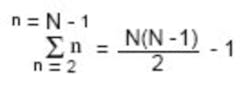
If this technique can be used, it provides considerable timesaving over direct implementation of the one-to-all-others test that requires 90 measurements for a 10-wire cable.
Confirming that a connection exists involves making a measurement to verify resistance smaller than a specified limit, typically a few ohms or less. The limiting value is determined by adding the resistances of the wire terminations to that of the wire and including sufficient margin to allow for manufacturing tolerances. An open circuit is defined by a similar resistance measurement but with a value greater than 10 k?, for example.
Precise Kelvin measurements can help determine how close a particular wire may be to the go, no-go limit. A four-terminal connection must be used to test heavy power cables or measure low resistances that are part of a wiring harness.
At higher currents, low-voltage testing also verifies ground continuity, but this safety-related capability usually is not found in a cable tester. In this test, a current from 1 to 30 A is applied to confirm the resistance of the ground connection and ensure that the conductor can support a large fault current long enough that a protective device can open the primary power circuit in an appliance, for example.
What Will Stress Reveal?
High-voltage testing beyond the voltage levels anticipated in a particular cable application should expose insulation weaknesses if they exist. According to technical information from Cirris Systems, brief high-voltage cable testing at three times the rated voltage of the cable assemblies has not been known to damage or degrade insulation. It is common in aerospace work to test at two times the operating voltage plus 1,000 V.
A Chatsworth Data Cablemaster applications note provides additional insight into high-voltage testing: �Primary to the construction and maintenance of aerospace cable/harness assemblies is the integrity of the insulating material. It is imperative that cable/harness assemblies withstand transient voltage surges and prevent corona discharge at the operating altitude of 60,000 ft�.2
�The purpose of a dielectric strength (hipot) test is to apply a voltage to the cable/harness higher than its operating voltage for a specific time to detect disruptive discharge current due to arcing through faulty insulation across an undesired discharge path or spark gap. In order to detect spark gaps of 0.01? to 0.04? at sea level, one must use a dielectric strength test voltage between 1.4 kV peak (1,000 VAC) to 4.2 kV peak (3,000 VAC). Furthermore, the dielectric strength test for aerospace vehicles is especially critical since dielectric breakdown for a given spark gap decreases as a result of decreasing atmospheric pressure at higher altitudes. At 40,000 ft to 60,000 ft, dielectric strength is reduced by 80% to 90%. In other words, at 60,000 ft, a 0.01? to 0.04?3 spark gap would breakdown at 100 VAC to 300 VAC.�
AC generally is used for dielectric strength testing, also called dielectric withstand voltage (DWV) testing, although either AC or DC at the correct level will produce equivalent test results. The AC peaks apply the maximum stress so the corresponding DC test must use a voltage higher than the AC rms value by the factor 1.414. In practice, 1,500 VDC is an alternative to a 1,000-VAC test.
Insulation resistance (IR) usually is measured using a DC voltage and after any DWV tests. This test helps gauge the integrity of the wiring insulation but, instead of looking for unintentional discharges, measures the low-level leakage current.
A high voltage applied between one wire and all others tied together causes an initial current flow to charge the capacitance formed by the conductors and the insulation between them. Additionally, some charge is stored within the insulation material itself as a polarization charge. Finally, a small constant leakage current flows, the measurement of which is the object of the exercise.
Some time after the initial charges occur, only the leakage current will be flowing. A DC IR test inherently settles to the final leakage current value after the transient currents have stopped. Some AC hipot testers are available with the capability to measure the real part of the total current and exclude the reactive capacitive current.4
Whether AC or DC is used for either DWV or IR tests depends on what was specified by the regulatory body that required the testing to be done. For both insulation tests, several military standards make clear that the one wire being tested is in relation to all other points tied together. This includes all other wires in the cable/harness as well as any shields and connector shells that may be part of the cable/harness assembly.
With cable/harness testing, as with most things, one level of testing does not apply across all situations. The IPC/WHMA-A-620 standard Requirements and Acceptance for Cable and Wire Harness Assemblies classifies wiring harnesses in three categories for which appropriate tests are being defined. When completed, the new test section will become part of a revision to the standard:
� Class 1�General Electronic Products
Consumer products, some computers/peripherals, hardware suitable for applications where the major requirement is the function of the completed assembly.
� Class 2�Dedicated-Service Electronic Products
Communications equipment, sophisticated business machines, and instruments where high performance and extended life are required, when uninterrupted service is desired but not critical.
� Class 3�High-Performance Electronic Products
Commercial/military products where continued performance/performance on demand is critical. Equipment downtime cannot be tolerated, uncommonly harsh environment where equipment function is required.
The degree of electrical testing proposed for the A-620 revision is shown in Table 1. Additional mechanical tests such as pull-force testing for crimp-on terminations and coaxial shields also are involved.
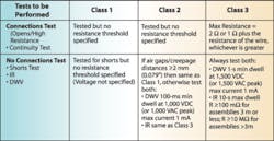
As the number of the cable classification increases, so does precision of the electrical tests.5 This effect reflects the level of cost that can be borne by applications associated with each of the three categories. For example, in many Class 1 consumer products, cost is nearly as important as function. In Class 3 products, the additional cost of thorough wire harness testing is small compared to the consequences of cable failure.
An alternative way of performing high-voltage insulation tests is an example of how high cable integrity and low cost can coexist. Testing each wire typically requires at least 10 s, and some regulatory bodies specify that the high voltage be applied for a minute or more. Whatever the dwell time per wire, the overall linear test time simply is the product of that time multiplied by the number of wires. It can take a long time to perform such a test.
A mass hipot algorithm available in Cabletest Systems products groups wires within the harness and applies the test voltage between the groups. By repeatedly regrouping the individual wires and retesting, all combinations of positive and negative voltage stress can be applied in much less time. Whether this technique can be used in lieu of the strictly linear definition is one more factor that affects the cost of test.
How Far Does a Cable Tester Go?
Many cable testers are only capable of performing Class 1 tests because they do not have a high-voltage test function. On the other hand, most dedicated IR measurement instruments, so-called meggers or hipot testers used for DWV testing, cannot quickly determine wire harness continuity like a cable tester.
The HypotULTRA III from Associated Research, when combined with up to five SC6540 modular scanners, can run high-voltage and continuity tests on wire harnesses with as many as 80 conductors. Why would you opt for this type of solution? If you need to apply test voltages much higher than 1,500 VDC, you have little choice but to use a hipot tester. This product provides up to 5 kV at 30 mA AC or 10 mA DC and can monitor true leakage current as well as detect dielectric breakdown arcing.
If your wire harness has several hundred conductors, then a cable tester with a high-voltage test capability probably is a better choice. Many DWV and IR tests are addressed by the 1,000-VAC or 1,500-VDC capability offered today by cable testers.
To use a high-voltage capability effectively, a cable tester must provide the associated timing, ramping or current limit, and safety features found in hipot testers. For example, if an AC DWV test is being performed, the total current can exceed a potentially lethal level, and ground-fault interrupters may be used to ensure operator safety.
DC testing does not involve such high currents. Even the initial charging transients can be greatly minimized by suitably limiting the output current or slowly ramping the output voltage.
Summary
There is an overlap between those functions traditionally associated with cable testers and hipot testers. Whether you must use one or the other or both is determined by the number of conductors in a wire harness and the level of test voltage required. If high-voltage testing at greater than 1,500 VDC is needed, a hipot tester is necessary; but if more than 80 wires are involved, you will need a cable tester as well.
These numbers are only approximate because vendors are constantly developing new instruments with increased functionality. This means that as cable test and hipot products continue to borrow capabilities from each other, more versatile equipment will become available. Cable testers with extended insulation testing features may have the means to perform both low-cost and rigorous A-620 testing in a single instrument.
References
1. Cable, Harness and Wiring Testing Information, Banair Electronic Engineers, Southampton, U.K., www.cabletester.co.uk
2. �Cable & Harness HiPot Testing for Military Applications (Aerospace Vehicles),� Cablemaster Applications Note AN9507-1, Chatsworth Data.
3. Ibid, the reference is made to Reference Data for Engineers Fifth Edition, Howard Sams & Co., pp. 41-1, 41-2.
4. Maccarone, R., �Cable Testing�An Overview,� Cabletest Systems, 2003.
5. �A-620 Cable Testing Standard,� Cirris Systems, www.cirris.com/~cirris/press/a-620_summary.html
June 2005
About the Author
Comment About the Article
To join the conversation, and become an exclusive member of Electronic Design, create an account today!

Leaders relevant to this article: