University students developed a methodology to test frequency shift in crystal oscillators during rocket flight.
Sounding rockets often are used by NASA as a cost-effective way to conduct investigations at specified times and altitudes. Experiments using these rockets provide a variety of information on the upper atmosphere, the sun, stars, galaxies, and planets. However, to gather this information as well as its location, the sounding rocket must communicate back to the launch site.
The FM-based communications scheme currently used by NASA sounding rockets is very expensive but also very forgiving in terms of center frequency drift. Conversely, a Tracking and Data Relay Satellite System (TDRSS) transceiver onboard the rockets would create greater launch-site flexibility and more robust communications between the rockets and the launch site�all at a lower cost.
There is a drawback to this arrangement. The TDRSS communications scheme loses the communications (COM) lock if a shift in the local oscillator (LO) frequency occurs.
A group of Electronic Engineering Technology Program students from Pittsburg State University has developed a method to test the acceleration-induced frequency sensitivity of a crystal oscillator as a precursor to designing an acceleration compensation system for the oscillator.
The research could help NASA create a stable TDRSS transceiver link on sounding rockets. NASA approved the project, which the students coordinated with the NASA Wallops Flight Facility for an upcoming flight onboard the NASA C-9 Reduced Gravity Aircraft. The C-9 has the capability to establish 30 seconds of 0 and 2 g conditions in the cabin during flight.
Oscillators in Motion
According to IEEE 1193-1994, the acceleration sensitivity of an oscillator is dependent on the direction of acceleration and other repetitive stimuli such as temperature, pressure, electromagnetic effects, humidity, and neutron radiation.1 A sounding rocket could expose an LO to as much as 30 g of acceleration, potentially causing loss of communications to the TDRSS and, therefore, loss of valuable information.
Even worse, this exposure could cause the rocket to lose command and control data. As a result, a device with the capability to monitor and quantify the acceleration sensitivity of a crystal oscillator is necessary to implement a cost-effective, stable TDRSS transceiver.
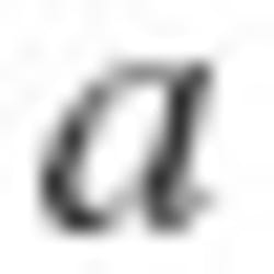
The team based its hypothesis on papers written by Raymond Filler for the IEEE Transactions on Ultrasonics, Ferroelectrics, and Frequency Control and by R.B. Haskell and P.E. Morley of Vectron International.2,3 Filler said the acceleration sensitivity (?) depends on the direction of acceleration and is effectively a vector quantity.
To find ?, researchers typically perform scalar measurements with equal accelerations in three mutually orthogonal axes. Then they derive spatial properties from those three measurements.2,3
The instantaneous frequency of a crystal integrated into an oscillator circuit can be described by:
Researchers have shown that if they mix the oscillator output with the output of a stable reference, they can relate g sensitivity to the resultant first-order sideband levels relative to the carrier frequency. This equation is
where: L = the relative sideband level in dBc
Researchers then can observe the resultant mixing and relative power levels of these two frequencies using a spectrum analyzer centered at the reference oscillator�s output frequency.3
Phase I Testing: Ground Tests
To quantify the acceleration sensitivity, the Pittsburg State University students first conducted lab vibration tests. They introduced a suite of 10-MHz crystal oscillators to various accelerations at Eagle Picher Industries in Joplin, MO.
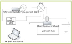
The students mixed the output signal of the crystal oscillator under test with a 10-MHz nonaccelerated reference signal via a frequency mixer. Then they monitored the height of the sidebands with the DAQPad-6016 Data Acquisition Device for USB and LabVIEW� software from National Instruments (Figure 1).
During testing, the automated system also monitored and recorded other environmental variables. This provided the capability to rule out other possible factors that could have affected the crystal oscillator output.
Due to the nature of the vibration table facility, the students were most concerned about two variables�magnetic field and electromagnetic interference (EMI)�in addition to acceleration. To null these effects, the students surrounded the crystal oscillator with mu-metal to shield it from magnetic fields and enclosed the oscillator and environment board in a specially designed EMI shielded box.
After performing ground-based tests with the configuration shown in Figure 1, the students plotted the output of the crystal oscillator under test against the acceleration and, using Equation 2, determined the g of each crystal that they subjected to the experiment.
Phase II Testing: Air Tests
NASA has accepted the students� project for the NASA educational program. During the second phase of testing in October, the device will undergo a real-world assessment onboard the NASA C-9 microgravity plane at Johnson Space Center in Houston. The microgravity plane will subject the crystal oscillator to periods of 0 to 2 g.
Once the flight has completed, the students will compare data obtained from the real-world C-9 test to the data obtained from the vibration table. Results from the periods of 0 and 2 g will be very important to the understanding and creation of a full acceleration response graph.
To accommodate Phase II data collection, the students will make some changes to the test setup. Rather than a single setup, they will implement two synchronized setups.
The ground setup will be located at Ellington Field and provide control conditions with respect to acceleration. It will include a reference oscillator with LabVIEW and an NI USB-based data acquisition device monitoring variables such as temperature, humidity, magnetic field, and acceleration.
The test setup onboard the C-9 aircraft will be a duplicate of the ground setup. The difference in acceleration as well as the frequency response of both oscillators will be the primary data of interest during the test.
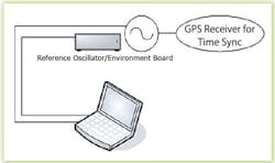
To make sure data from both oscillators is properly correlated for analysis, the students will need to synchronize the data acquisition operations from the reference setup and the crystal onboard the C-9. For this phase of testing, the students will add two GPS receivers to provide time synchronization between the systems (Figure 2).
Summary
NASA currently uses an FM-based data transmission system onboard its sounding rockets. Because many of these sounding rockets carry payloads that are irrecoverable, it is imperative that the data relayed back to the ground station be very reliable and uninterrupted.
The use of the current FM-based data transmission system requires data transceivers to be located near every launch site. This system still has the drawback that communications are lost as the rocket passes the horizon.
A TDRSS transceiver placed onboard each sounding rocket would provide a cheaper, more efficient method of transmitting data back to earth. However, the spread-spectrum phase-modulated communications scheme used by TDRSS requires a very stable oscillator as a reference. The current generation of TDRSS transceivers used onboard the shuttle and other vehicles provides that stable reference, but these new transceivers are far too expensive to use in a nonrecoverable payload such as that carried by many sounding rockets. To solve this problem, scientists need to develop a TDRSS transceiver that could be based around inexpensive quartz crystal oscillators.
In gentle environments, these crystals are very stable. However, sounding rockets produce high accelerations and can subject a payload to accelerations upwards of 30 g, causing the crystal�s frequency to shift and disrupt the communications link.
The goal of this research was to establish a cost-effective, repeatable test to quantify the amount of frequency shift under a given acceleration condition. It is hoped that these test apparatus and procedures will be used as a foundation for further research into the phenomenon of acceleration-induced frequency shift in crystal oscillators.
This system will gather data to facilitate the design of a low-cost TDRSS transceiver based on a crystal oscillator reference. The next step is to use the data collected to develop a TDRSS transceiver that provides compensation for any acceleration-induced frequency shift.
Acknowledgement
The authors wish to thank Pittsburg State University; NASA Wallops Flight Facility; Dr. James Lookadoo, EET professor; Pittsburg State University Microgravity Flight Office; and Johnson Space Center for their contributions to this effort.
References
1. IEEE Guide for Measurement of Environmental Sensitivities of Standard Frequency Generators IEEE 1193-1994, Frequency Control Specifications and Standards, 1995, Oct. 9, 2004,
www.ieee-uffc.org/freqcontrol/fc_standards.html
2. Filler, R.L., �The Acceleration Sensitivity of Quartz Crystal Oscillators: A Review,� IEEE Transactions on Ultrasonics, Ferroelectrics, and Frequency Control 35.3, 1988, pp. 297-305.
3. Haskell, R.B., and P.E. Morley, �Method of Measurement of the Sensitivity of Crystal Resonators to Repetitive Stimuli,� Vectron International Application Notes, Vectron International, October 2004, http://www.drxm.com/products/appnotes/g_measurement.pdf
About the Authors
Jacob Stich recently graduated summa cum laude with a B.S. degree in engineering technology and a minor in business administration from Pittsburg State University. He was named the State of Kansas Student Employee of the Year in 2005 and has accepted a position with Caterpillar in Peoria, IL. Mr. Stich anticipates being able to participate in the actual microgravity flight in October.
Randy Winzer is an associate professor in the electronics engineering technology program at Pittsburg State University and has served as the program coordinator since 2003. He holds B.S. and M.S. degrees in engineering technology. Pittsburg State University, Department of Engineering Technology, Pittsburg, KS 66762, 620-235-4370, e-mail: [email protected]
FOR MORE INFORMATION
on TDRSS
www.rsleads.com/508ee-176
August 2005


