A DSP IC is more than a microprocessor on steroids. The architecture�s different.
Convergence often is used to describe the growing areas of overlap among computing, communications, and consumer electronics. But, convergence also exists more generally at a lower level between hardware and software. In many cases, it�s difficult to distinguish between the two disciplines given the diverse capabilities of digital signal processing (DSP).
DSP devices make possible performance that analog hardware on its own cannot achieve and improve product flexibility. Including a DSP IC in a system�s architecture can greatly influence hardware/software implementation decisions. And, because DSP devices operate very quickly with high precision, complex algorithms become practical that otherwise would execute too slowly on a general-purpose microprocessor.
Several examples showing the use of DSP in test instruments illustrate the wide range of benefits these ICs provide.
Can You Hear Me Now?
In the JDSU HST-3000 Hand-Held Telecoms Tester, a DSP IC supports field upgradeability, runs several types of signal-processing algorithms, and implements a variety of voice over IP codecs. �A great benefit of using a DSP device is flexibility in the field,� commented David Smith, a senior electrical engineer at JDSU. �On several occasions, we�ve added new measurements to fielded equipment just by upgrading the customer�s software. Other benefits include higher execution speed provided by single-cycle floating-point operations, higher native accuracy, and less need for large memory storage.
�A fast floating-point DSP IC can use its built-in direct memory access (DMA) support to capture each sample from the ADC. The algorithm can completely process the sample and save the result in a single variable. No data arrays are needed in this example,� he explained, �so RAM memory usage is kept small. The native floating-point operations are so accurate that we seldom worry about noisy or unstable digital filters or other iterative processes. If we need to ensure very low numerical noise, we can use 64-b double-precision floating-point operations with only a small speed penalty.�
In the HST-3000, the DSP device really does earn its keep. In addition to handling all types of digital subscriber line (xDSL) modulation and demodulation, complementing hardware in a copper analog tester function, and generating a wide range of test signals, the DSP device runs built-in self-test (BIST) and self-calibration routines. The BIST capabilities are applied after production when the board is first powered up. If there is a problem, 140 diagnostic tests measure all transmitter and receiver circuits, the power supplies, clocks and relays, and most of the DSP functionality.
In this volume-, cost-, and power-sensitive application, JDSU used a DSP IC to achieve overall performance that couldn�t be matched with any other approach. As Mr. Smith put it, �DSP devices are all about multiplying and accumulating fast. Throw in dual-access on-board SRAM, multiple DMA channels, and a few timers, and you�ve got a real hot-rod processor. Fixed-point microprocessors cannot come close to the rate achieved for single-cycle multiplies with accumulation.�
Reference Waveform Generation
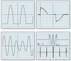
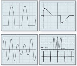
The need for accurate electrical energy measurement has driven many countries to mandate periodic energy-meter calibration. In addition to sinusoidal test signals, which traditionally have been used to allow accurate sensing and control via feedback, waveforms such as those shown in Figure 1 also must fall within a meter�s capabilities. These examples are taken from EN 61036:1997 Alternating current static watt-hour meters for active energy now replaced by EN 62053-21:2003 Electricity metering equipment (a.c.). Particular requirements. Part 21: Static meters for active energy and indicative of the kinds of commonly occurring nonsinusoidal waveforms that must be accurately measured.
EN 62053:2003 contains several sections that deal with aspects of electrical energy-meter manufacturing. Part 21 covers electricity supply meters, electric power measurement, alternating current, type testing, rated frequencies, electric terminals, leakage paths, clearance distances, marking, working environment, accuracy, and testing. Different product classes specify the rated accuracy. For example, Class 1 is 1% accurate at nominal load and power factor.
If the accuracy of an energy meter is to be verified to some specified percentage, the test signal needs to be even more accurate. �In the Fluke 6100A Electrical Power Standard, DSP technology provides the framework within which digitally constructed analog signals are dynamically corrected to provide high accuracy in all components of voltage and current waveforms,� said Geoff Ives, business systems and projects manager at Fluke Precision Measurement.
�The analog output is sensed and fed back via an ADC. The output of the direct digital synthesis (DDS) system is modified to correct phase angle and amplitude errors,� he explained. �Fluke was granted a patent for this technique in 2003. It covers the use of a DSP device in an active feedback loop to correct amplitude and phase of each harmonic. In the development of the 6100A, the most significant step was finding a device that combined high speed, low overhead for access to external memory, and good development tools and support.�
Extensive Functionality At Low Cost
Low cost is good when it applies to test instruments, but it�s even better when it also relates to the development project that designed the instruments. This situation describes a recent Agilent Technologies effort to address instruments used in manufacturing test.
�Low cost and fast execution of the measurements are key features of such instruments,� explained Joeri Melis, an R&D engineer at the company. �In one of the units, an embedded DSP IC is used to analyze captured waveforms containing wireless area networking/personal area networking (WAN/PAN) signals. An Analog Devices Sharc DSP device processes one or several captured bursts in a non-real-time mode.
�The DSP software was ported from existing general-purpose software running in a PC-based environment. The aim was to require a minimal amount of design work while still providing all the features of the general-purpose software,� he continued. �Some flexibility was traded off to minimize memory usage and maximize the measurement speed but only where the WAN/PAN signals didn�t require flexibility. The DSP device does all signal-related processing ranging from simple spectrum analysis to full demodulation.�
The DSP IC used was a fairly low-end floating-point model that made it possible to rapidly port general-purpose software to a low-cost instrument. Overall, the resulting product improved on an earlier non-DSP approach in several ways. Using a DSP IC meant that fewer components were required to perform the measurements. In addition to greater reliability resulting from a reduced number of connections, the quantity of data transfers also was reduced with the benefit of shorter measurement time.
Extending Oscilloscope Performance
DSP devices have become fast enough that they are addressing high-speed data acquisition applications. A good example is the use of DSP ICs in digital storage oscilloscopes.
For minimum signal distortion, an amplifier�s frequency response must exhibit constant gain and linear phase. Linear phase corresponds to a constant group time delay, which means that all frequency components of a signal at the input to an amplifier remain in the same relationship to each other after amplification. These gain and phase conditions are not completely satisfied in traditional oscilloscopes.
Many scopes approximate a Gaussian filter response, which features gradually decreasing gain and a nearly linear phase. A pulse input to a Gaussian filter will show no overshoot at the output. However, the transition region from passband to stop band in the magnitude vs. frequency characteristic is very wide. This causes measurement errors for frequency components in the scope�s passband faster than about 20% of the bandwidth.
Modern DSOs no longer support the familiar rise time = 0.35/bandwidth rule of thumb that applies to scopes with a Gaussian high-frequency response. Today�s fast DSOs behave differently with rise time = 0.40/bandwidth or 0.45/bandwidth being more representative. A slower rise time is a consequence of a narrower transition region that allows the stop-band asymptote to be reached quickly. In other words, these scopes have a sharper corner in their magnitude vs. frequency characteristic. This means there is less high-frequency energy available after the -3-dB point than with a Gaussian characteristic.
In a high-frequency DSO, the stop-band attenuation must be sufficient to avoid aliasing because alias components cannot be removed after they have been created. However, when the instrument bandwidth is close to the Nyquist frequency, as in high-performance DSOs, a very fast rate of attenuation in the stop band is implied.
Achieving both linear phase and a flat magnitude in a wide-bandwidth sampled data application typically requires a very accurate, expensive, and difficult-to-manufacture high-order analog filter. An alternative approach accepts the inaccuracies of a less demanding response and uses DSP to compensate for the errors in the digitized signal. Of course, the overall response is affected by all parts of the signal path from the input preamplifier and attenuator through the ADC itself.
DSP in LeCroy Scopes
The use of DSP techniques in LeCroy scopes was discussed in detail by Peter J. Pupalaikis, the company�s principal technologist. �We use DSP for correction of the magnitude and phase characteristics of the front-end amplifier and digitizer. Making these circuits with a flat magnitude response out to 10 GHz is nearly impossible in hardware alone. Also, to compensate the phase and magnitude responses, some of our infinite impulse response (IIR) filters are very large, having 60 poles and zeros. That level of complexity isn�t practical in hardware.�
Mr. Pupalaikis described an unconventional approach to very high-frequency scope design. �In our highest performance instrument, we use a combination of RF and microwave circuitry with a DSP to double the bandwidth of the oscilloscope. The input signal is separated into multiple frequency bands and down-converted using the RF front end. After the signal is digitized, we put it back together using DSP techniques.
�The concept of splitting the signal into frequency bands and down-converting has its origins in the early 1900s, but doing this over wide frequency bands with any degree of fidelity is extremely difficult. DSP technology enables this approach to be used, which otherwise would be impossible,� he explained. �We also use DSP to correct interleave artifacts, errors caused when multiple digitizers are combined together to achieve a higher sample rate. Errors occur when the frequency responses of interleaved digitizers are not matched.�
In many signal-processing algorithms including filtering, multiply-accumulate operations are common. The Pentium processor, although not usually considered a DSP device, actually is quite a good one with very fast multiply-accumulate capability. �Two of the Pentium�s important DSP acceleration capabilities are multimedia extensions (MMX) and streaming SIMD exten-sions (SSE) where the SIMD acronym means single instruction/multiple data,� Mr. Pupalaikis continued.
�SSE and SIMD perform multiple data operations with a single instruction, such as four multiply-accumulates in a single clock cycle. Using the MMX and SSE extensions, we achieve approximately 10 billion floating-point operations per second. With the long acquisition memories in some of our scopes and the fact that up to 3,000 floating-point operations are required per data point, it�s clear that high speed is very important.�
DSP in Tektronix Scopes
As you might expect, if one scope company is using DSP technology to extend bandwidth and generally correct response artifacts, other companies also are doing it. In fact, a recent Tektronix white paper, DSP in High-Performance Oscilloscopes, deals entirely with this subject. It should be noted that Tektronix scopes with enhanced bandwidth treat inputs as baseband signals.
The paper covers bandwidth enhancement in detail, including specific examples showing the before and after responses of several scope models. Because this white paper was developed using test results from prototype instruments, the detailed scope response waveforms are not necessarily indicative of production instrument performance. Nevertheless, a number of factors are highlighted that contribute to the difficulty of implementing this type of response correction.
Tektronix uses an arbitrary finite impulse response (FIR) digital filter to compensate the passband response. In this context, arbitrary means that the filter coefficients are calculated based on calibration data and can be different for each channel and voltage range on every scope.
One of the benefits of DSP-based response correction is the normalization of passband and stop-band characteristics across all channels in one scope as well as across all scopes of a particular model. This means that you can much more easily make repeatable measurements on different units of the same model scope, for example in a production environment, and that measurements from different channels can be directly compared.
DSP-based bandwidth correction does have its limitations, noise being one of them. Bandwidth enhancement flattens the passband response and boosts the stop-band response up to the new, higher bandwidth. This means that the amplitudes of frequency components on both sides of the original -3-dB point are increased, and higher noise may result depending on the characteristics of the amplifier at those frequencies.
Some other interesting effects are collectively termed Gibbs Phenomena. You may recall running into this mathematical curiosity when studying the Fourier series. All functions of time can be represented by the summation of a number of sinusoids at different frequencies except at points where the functions are discontinuous. At discontinuities, preshoot and overshoot occur accompanied by damped oscillation. In the late 1800s, J. Willard Gibbs first explained why this was happening, and these effects subsequently were called Gibbs Phenomena.
More generally, the term Gibbs Phenomena has been applied to similar appearing effects caused by insufficient bandwidth. A fast rising or falling edge implies high-frequency components, and these extend to either side of the edge. Although we view such edges as being entirely causal in the time domain, in terms of Fourier series frequency components, the high-frequency components must exist both ahead of and after the edge. The summation of higher frequencies with exactly the right phases is required to generate the corners at the beginning and end of the edge.
If the highest frequency components of a real edge are attenuated because of a scope�s insufficient bandwidth, for example, the rise time of the edge is slowed down. But, that�s not all that happens. Without the correct components to combine with lower frequencies, ringing, preshoot, and overshoot will accompany the corners of the signal edge.
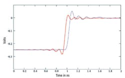
Figure 2 compares prototype Tektronix TDS6804B responses to a 15.5-ps step with and without bandwidth enhancement. This very fast signal requires frequency components beyond the scope bandwidth for its accurate reconstruction. There is simply not sufficient bandwidth to correctly represent the step signal.
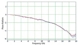
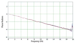
Digging a bit deeper into the corrected and uncorrected phase response of a TDS6154 helps to explain the edge appearance in detail. From Figures 3a and 3b, it�s clear that bandwidth enhancement has made a large difference to phase linearity. Figure 3b shows a linear phase shift of about 12.1 degrees/gigahertz, corresponding to a constant group time delay of 33.5 ps.
However, the slope of the curve is a function of the manner in which it was plotted. The important thing is not the value of the slope but rather that the phase response is linear and the corresponding time delay is constant.
In comparison, the uncorrected phase response implies a variable delay vs. frequency. A delay of 2 radians at 12 GHz corresponds to 26.5 ps, but a delay of 4 radians at 17 GHz is equivalent to 37.5 ps. Although these values may not represent actual instrument performance, the uncorrected phase response does show that higher frequency components of a fast edge are delayed more than the lower frequencies, causing only an overshoot to appear in the uncorrected display.
Gibbs Phenomena manifest themselves when the bandwidth of a linear phase system is too small compared to the signal being handled. For example, Gibbs Phenomena are discussed in articles on audio amplifier transient response. They are not limited to gigahertz bandwidths.
Without phase correction via DSP-based bandwidth enhancement, most hardware amplifiers have a phase characteristic similar to that shown in Figure 3a: The phase lag and corresponding time delay increase with frequency in the stop band beyond the -3-dB point. This is the reason that we usually don�t see signal preshoot as shown in Figure 2.
Commenting on the use of DSP in scopes, Marv LaVoie, a Tektronix Fellow, stressed the balance required between digital and analog design. �Typically, DSP-based enhancements improve oscilloscope performance by providing increased bandwidth, faster rise time, and flatter frequency response and give greater measurement accuracy. However, DSP effectiveness in these instruments depends on the high quality of their analog circuitry. DSP alone cannot overcome analog design shortcomings.�
Sin (x)/x Interpolation
Another scope-related use of DSP technology is sample interpolation. Many approaches have been used to form acquired data points into a reconstructed copy of the original analog waveform. The simplest technique draws straight lines between successive points. While this linear dot joining or interpolation helps you to group the sample points in the correct order, the displayed image seldom has the appearance of a smooth signal.
Sine interpolation, or more rigorously sinc interpolation related to the sin (x)/x sinc function, helps to solve the problem. Claude Shannon and others have proven mathematically that a periodically sampled, band-limited, continuous function of time is equal to the sum of a series of sinc functions with the delays and amplitudes of the data samples. Sinc-interpolated waveforms don�t just look better, they can be accurate as well.
|
FOR MORE INFORMATION |
| Agilent Technologies | Agilent Open Test Instruments | www.rsleads.com/606ee-176 |
| Fluke | 6100A Electrical Power Standard | www.rsleads.com/606ee-177 |
| JDSU | HST-3000 Telecoms Tester | www.rsleads.com/606ee-178 |
| LeCroy | WaveMaster 8000A Series Oscilloscopes | www.rsleads.com/606ee-179 |
| Tektronix | TDS 6000 Series Oscilloscopes | www.rsleads.com/606ee-180 |
�Sin(x)/x waveform interpolation is used to reconstruct the incoming waveform with higher timing resolution than the maximum real-time sample rate,� explained Tektronix�s Mr. LaVoie. �The TDS6124C and TDS6154C use sin (x)/x interpolation techniques to extend timing resolution beyond the 25-ps/point (40-GS/s) maximum real-time rate to 500 fs/point, equivalent to 2 TS/s.�
Sinc interpolation is based on the original signal being band limited. This means that all frequency components beyond a certain value have zero amplitude. For this discussion, the frequency limit is a scope�s bandwidth. Under that condition, higher timing resolution can be very useful. However, if a signal is not completely band limited, for example in the case of a fast transient, then you cannot assume that the interpolated points actually represent the input waveform, regardless of their greater time resolution.
Further DSP Applications in Scopes
Beyond the use of DSP devices to modify a scope�s basic amplifier response and improve time resolution for display and measurement purposes, Mr. LaVoie listed several other roles for these fast computing elements. For example, many scopes provide an FFT mode in which sampled data points in the time domain are transformed into spectral data in the frequency domain.
A DSP IC also detects the peaks within the ADC output data stream. Although the time-base selection determines the period between stored samples, initially inputs are sampled at the highest direct sampling rate supported by the instrument. This means that a sample is much more likely to fall on or very near a peak. Peaks so identified are preserved during decimation from the highest sampling rate to the selected rate as the acquisition record is stored. Subsequent data compression for display also retains peaks.
A third use of a DSP device in scopes is implementation of a specified frequency response for testing purposes. For example, optical reference receivers used in fiber-optic communications testing must comply with a precise filter characteristic based on the data rate being used. Mr. LaVoie said, �Calibration of the entire input channel with the proper fourth-order Bessel-Thompson response is the key characteristic of a reference receiver. This calibration must be appropriate for the exact data rate and standard being tested.
�The CSA7404B uses DSP technology to exactly tailor the optical system�s response for the specific standard selected,� he continued. �Trying to duplicate this capability in hardware is virtually impossible due to the number of components required to support all the standards built into the instrument. Connecting the proper components and recalibrating the input channel for each standard would be prohibitively complex.�
A final scope-related DSP-based application involves spectrogram capability for ultrawideband (UWB) signal analysis. According to Mr. LaVoie, The TDS6000C scope models have an available UWB program to capture and characterize these 3.1-GHz to 10.6-GHz signals. A DSP IC is used to down-convert the UWB RF signal, determine its band group, and verify which of the frequency-hopping patterns is being used.
The program also transforms the waveform data to a spectrogram that displays changes in frequency and power over time. In addition, DSP is used in demodulating the RF waveform, displaying the constellation patterns, and measuring the UWB radio�s error vector magnitude.
Conclusion
A large number of DSP-related solutions have been described during the discussion of several test-instrument applications. Today�s DSP ICs offer a diverse range of capabilities, so choosing the right device for your application is critical. In fact, as the LeCroy example shows, DSP extensions to a high-end microprocessor may suit your needs better than a separate, dedicated DSP device.
Good software can ring out every ounce of hardware performance possible. Nevertheless, precise, rugged, accurate, and stable hardware is the foundation of a state-of-the-art instrument. If the software/hardware balance is right, an instrument user simply enjoys the increased benefits DSP technology has made possible.
June 2006
