Two major approaches are taken to optical fiber signal switching: One involves conversion to and from an electrical form and one doesn�t. The optical-electrical-optical (OEO) terminology clearly implies the conversion from one form to another.
This type of switch has been used for many years and has the advantage of being based on trusted technology. It also provides the opportunity for per-signal amplification and resynchronization and offers a means of delaying the signal while routing information is being decoded. Against those positive aspects, OEO approaches are band-limited by the electronics involved in the O-to-E and E-to-O conversions.
The consequences of this limitation are apparent as faster and faster data transmission standards are adopted such as Ethernet�s 100-Mb/s to 1-Gb/s to 10-Gb/s to 40-Gb/s ongoing performance increase. OEO networks aren�t easily adapted to faster operation. The hardware must be replaced.
For a truly bandwidth-independent switch, an optical-optical-optical (OOO) structure is required. If no conversion takes place, there is no signal bandwidth limitation.
Indeed, all-optical switching is totally modulation-agnostic. The light leaving one fiber and entering another may be attenuated slightly by the intervening switch, but information carried by modulated wavelengths is not affected. A number of different technologies are used in optical switches.
Micromirror Technology
When a large number of fibers must be reconfigured, as in a communications network or in more recent fiber to the curb (FTTX) applications, the most economical switching arrangement is an NxM array. Larger versions of these switches can handle several hundred inputs and outputs. In a nonblocking matrix, any input can be switched to any output.
Large matrix switches alter the physical signal path either through reflection or deflection. One technique typically uses two arrays of micromirrors to define the path between the input and output fibers. Light beams happily cross through each other without interference, and this property is fundamental to these 3-D free-space optical systems.
The individual mirror angular displacement is controllable over a range of �1 or �2 degrees. Nevertheless, the mirrors are small enough and the distances among the switch components relatively large enough that a signal at one corner of the matrix can be redirected to reach the output fiber at the opposite corner.
The micromirror concept was invented in 1987 by Dr. Larry Hornbeck at Texas Instruments (TI) and now is the basis of a large projection display business. However, the TI mirrors operate in a digital manner: A mirror is tilted in one direction or the other and acts like an on-off switch. There is no attempt to control the mirror�s position between the two extremes. In addition, because up to two million mirrors are used to preserve image detail, each mirror is much smaller than those used in fiber-optic switches.
In an optical matrix switch, a mirror�s position must be continuously variable and accurately controllable. One way that companies have addressed the stringent requirements is to wrap a control loop around the mirror drive circuitry with a small portion of the optical signal used for feedback. In this way, the mirror position is automatically adjusted to maintain the maximum signal intensity regardless of disturbances associated with vibration or temperature.
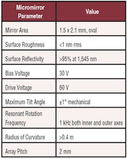
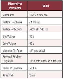
The micromirrors in these types of switches generally are based on MEMS technology. As an example, specifications for an array of micromirrors manufactured by Colibrys are listed in Table 1. The surface flatness and roughness must be of very high quality to ensure low optical losses within the switch. Both surface roughness and excessive mirror curvature tend to broaden the beam, reducing the amount of light incident on the output fiber (see sidebar).
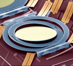
Figure 1 shows a circular micromirror that is used in Alcatel-Lucent optical switches. The mirror is gimbaled so that it can simultaneously deflect in two directions. Of particular importance are the large, low-stress hinges designed to maintain alignment and ensure very long mechanical life. All micromirrors used in optical switches have similar requirements, but of course, different manufacturers address them in various ways.
Glimmerglass has developed a range of switches based on proprietary Brilliance� Micromirror Technology with up to 190 channels. Larger applications are addressed by combining multiple modules. These switches are being used in commercial networks as well as in network test labs.
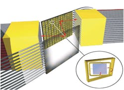
Calient also makes a micromirror-based optical matrix switch with up to 320 individually controllable mirror elements. The company�s DiamondWave� Switches use this technology, are certified to network equipment building system (NEBS) level 3, and come in sizes from 8×8 to 320×320 ports (Figure 2).
Although primarily targeted at communications networks, these devices are finding application as remotely programmable cross-connect switches in FTTX installations. Such a switch can be configured to enable remote optical fiber monitoring, testing, and troubleshooting as well as simply to rearrange in/out connections. Obviously, significant cost savings could be achieved if a large percentage of traditionally required truck rolls were avoided.
Piezoelectric Actuation
Polatis (Cambridge, U.K.) and Continuum Photonics (Billerica, MA) merged in mid-2005 and are promoting OOO switches based on the company�s DirectLight� Beam-Steering Technology. In this approach, separate piezoelectric elements support and deflect individual lenses.
According to the company, a piezoelectric actuator can provide forces more than four orders of magnitude greater than the electrostatic forces used in micromirror arrays. Although the actual forces are somewhat reduced because the element�s motion must be amplified, the beam steering technique nevertheless exhibits high mechanical stiffness. This means that the mechanism is less susceptible to perturbations caused by vibration or temperature.
Light entering on a fiber is collimated and deflected by tilting the appropriate lens. A corresponding lens/collimator arrangement receives the deflected beam. The Polatis switch achieves high initial accuracy through calibration. Any offsets or small misalignments created in manufacturing and packaging the switch matrix are nulled by appropriately driving the active collimators. In addition, the insertion loss (IL) of each connection pair is kept low by actively monitoring the power level.
In contrast to position sensing used during the transition of a micromirror element from one position to another, piezoelectric beam steering operates open-loop. The final, precise path alignment is optimized in each type of system by a feedback loop based on optical signal intensity.
DirectLight switches are available in an optical switchblade format configured as 4×4, 4×8, or 8×8 in/out ports. In addition, these sizes as well as larger switches are packaged as rack-mount systems and modules. Polatis switching products are distributed worldwide by JDS Uniphase, now JDSU, through a 2005 agreement.
Electromechanical Actuation
Both the micromirror and piezoelectric technologies are forms of electromechanical systems. However, there are other types of less well-integrated switch actuators.
Typically, optical component testing requires only a few fibers and, for that reason, smaller capacity switches. Smaller sizes of Glimmerglass and Polatis switches are used in test applications, but in many cases having even four channels is overkill.
Agilent Technologies
Agilent has three optical test platforms: the 8163A/B Lightwave Multimeter with two slim module slots for the characterization and evaluation of optical components, the 8164A/B Lightwave Measurement System mainframe with one large and four slim module slots, and the 8166A/B Lightwave Multichannel System with 17 slim module slots. The 8159xB Series of modular optical switches is compatible with all three platforms.
The actual switch modules include an SPDT (81591B), an SP4T (81595B), and a 2×2 multiplexer (81594B crossover) switch. These are used to test optical and network components. For single-mode fibers, IL ranges from <1.0 dB (81591B) to <2.0 dB (81595B). Multimode IL is <1.0 dB for all switch configurations.
Cytec
Both multimode and single-mode optical switches are available within the company�s FO Series Passive Fiber-Optic Switching Systems. These switches come in 1×2, dual 1×2, and dual 1×2 nonblocking configurations. They use a moving fiber design that features accurate direct fiber-to-fiber connections. Because of the minimal number of fiber interfaces in the switch and the lack of connectors on the fibers, the low-loss versions of the switches achieve 0.25-dB IL for single-mode and 0.1-dB IL for multimode fibers.
The FO Switching System includes multiplexers and matrices based on these switch modules. All chassis have front-panel LEDs to indicate switch status. Connectors may be selected from ST, SC, and FC standard choices and extend from the rear of the chassis.
EADS North America Defense Test and Services
Four switch modules in the company�s 1260 Series cover 1×2, 2×2, 1×4 or dual 1×4, and 1×8 topologies. The smaller switches use the moving prism approach. Instead, the two larger modules have a moving armature that positions the common fiber collimator opposite the selected output fiber collimator. Diffraction-limited collimating lenses are used to ensure precise switching. All switch types specify IL at 0.6 dB typical, return loss (RL) from 55 to 60 dB, and 80 to 90 dB isolation between channels.
EXFO
The IQS-9100 Optical Switch Series includes several configurations: 1×2, 1×4, 1×8, 1×12, 1×16, 1×24, 1×32, 2×2, and 2×4. All single-mode models have from 0.5 to 0.7 dB IL typical and switch in 25 ms. The 1×4 and larger models also require an additional 425-ms debouncing time.
These switches and a large number of optical modules such as power meters, light sources, lasers, and variable attenuators are available for use in the company�s Windows 2000 Professional-based IQS-500 Intelligent Test System. The main chassis has an 8.4″ color touch-screen display and local controls for all the modules. Expansion units support a system with as many as 100 modules in total.
JDSU
JDSU has made many types of optical switches for several years. The larger switches with 100 or more channels are operated by stepper motors and feature a selection of latching and nonlatching models. This technology is relatively large but provides excellent switching characteristics. IL typically is 0.5 dB and RL >60 dB for single-mode fiber.
Small channel count switch modules such as the company�s SW series are available in 1×1, 1×2, 2×2 crossover, and 2×2 bypass configurations. As described in the SW Series datasheet, �The switch redirects the optical signal into a selected output fiber. This action is achieved using optical prisms driven by a high-precision nonlatching mechanism and activated by an electrical control signal.�
Keithley Instruments
The Keithley Series 7000 Mainframe accepts more than 40 types of switch/control cards including the Model 7090 1xN Series of optical switches. All but one of the seven switches use single-mode fiber. Model 7090-8-4 is a single-channel, eight-way multiplexer for multimode fiber. It comes with FC/SPC connectors, but for single-mode models, you can choose FC/SPC or FC/APC.
Newport
Newport offers component-style switch modules with 1-m long jacketed fiber pigtails and a choice of connector type. The switches use a moving prism between fixed collimator pairs, allowing bidirectional operation. The units are nonlatching and require a 5-V switching voltage.
Pickering Interfaces
Pickering makes the 810, 815, and 820 ranges of optical switch modules based on the JDSU SW Series Switches. You can choose FC/APC, FC/PC, and SC/PC types of connectors as well as switch configuration and number of banks. For example, the Model 20-810-144-M is a quad four-channel multiplexer for multimode fiber. In other words, there are four independent SP4T switches in a module.
Three new groups of single-mode fiber switches designated 850, 855, and 860 use MEMS mirror technology to achieve faster switching speed and smaller size. Switch reliability has not been compromised by the technology change. These switches and the earlier models plug into the company�s System 20 Chassis.
Comparing the older electromechanical switches to the newer mirror-based products, IL reduced from 1.5 dB typical to 0.8 dB typical, repeatability changed from �0.005 dB maximum to �0.01 dB maximum, switching time reduced from 15 ms maximum to 1 ms maximum, and the cycle rate increased greatly from 5/s to 500/s. In addition, the small form factor LC and MU connectors have been added to the available types.
Conclusion
Just as switching is integral to electrical test systems, so too is it required in optical testing. Most approaches achieve extremely low crosstalk, operate in 10 ms to 20 ms, and have low power requirements. Nevertheless, there are exceptions and trade-offs you may need to consider.
For example, some electromechanically actuated switches are latching. In the event power is lost, the switch will not change position. Also, some switches operate much more quickly than 10 ms: Pickering�s newer mirror-based switches can sustain 500 switching cycles/s. Equally, some switches require much longer settling time and switch more slowly than 10 ms.
Technology used in very large communications network switching applications has filtered down to both network and component test. Smaller test setups can benefit from the stringent qualification these network switches have undergone. Both micromirror and piezoelectrically positioned switches are available in four- or eight-channel increments.
The availability of new technology is important, especially in applications requiring long life or just a very high number of switching cycles. JDSU commented in the SKB Series Large Channel Count Switch Module datasheet that this was the only stepper-motor based switch module with a lifetime greater than 120 million cycles or more than 108. For this type of technology, 108 represents high reliability.
In contrast, Calient products based on the company�s DiamondWave micromirror approach are specified to have a 12-year mean time between failure. Glimmerglass� Vice President Advanced Networking Dr. Joe Parker said that there has never been a micromirror failure in the field. The hinge design and minimal angular deflection result in a maximum stress 500 times below single-crystal silicon�s yield stress. The switch�s reliability has been confirmed by billions of cycles of accelerated life testing, again without failure.
A large number of switching solutions are available for optical test systems being designed today. Longer term, as communications networks become more completely optical in nature, large-scale switching technologies will be even more reliable and affordable. And, as the optical communications component business grows, so will your need for multisite testing, enabled by advanced optical switching.
|
FOR MORE INFORMATION |
| Agilent Technologies | Model 81595B Switch | www.rsleads.com/705ee-176 |
| Calient Networks | DiamondWave AFM Switch | www.rsleads.com/705ee-177 |
| Colibrys | Micromirror Array | www.rsleads.com/705ee-178 |
| Cytec | FO Series Switches | www.rsleads.com/705ee-179 |
| EADS North America Defense Test and Services | 1260 Series Switches |
www.rsleads.com/705ee-180 |
| EXFO | IQS-9100 Optical Switch Series | www.rsleads.com/705ee-181 |
| Glimmerglass | Intelligent Optical Switches | www.rsleads.com/705ee-182 |
| JDSU | Mechanically Actuated Switch Modules | www.rsleads.com/705ee-183 |
| Keithley Instruments | Model 7090 1xN Series Optical Switches | www.rsleads.com/705ee-184 |
| Newport | Switch Modules | www.rsleads.com/705ee-185 |
| Pickering Interfaces | 8xx Series Optical Switches | www.rsleads.com/705ee-186 |
| Polatis | DirectLight Switches | www.rsleads.com/705ee-187 |
May 2007
