Development of MEMS relays has been underway since at least the early 90s with many types reported during the intervening years. Anticipated benefits include extremely small size, long life in excess of 100 billion cycles for military applications, high operating speed, and excellent RF characteristics. Unfortunately, the step from a working laboratory device to a reliable volume-manufactured product has proven to be large.
In addition to technical challenges, bringing any new technology into an existing market can be difficult. As John McKillop, chief technical officer at TeraVicta Technologies, explained, “The market generally requires an entry-level product that meets or exceeds the reliability, cost, and performance of the incumbent product. This creates a particularly difficult barrier for the entry of MEMS into the market because the relays most vulnerable to replacement are, on average, fairly reliable and low cost and have low actuating voltages.”1Today, only a few companies have proven MEMS switches or relays. Among them are TeraVicta, Radant MEMS, MEMtronics, and XCOM Wireless. These companies have developed MEMS products, but other devices may exist that have not been publicized. In addition, some MEMS relays have been introduced and subsequently withdrawn, such as the MagFusion products.
A few microminiaturized relays also have been developed. Advantest produces electrothermally activated relays for the company's own use in ATE. The advantages of the device include a very small 4-mm x 5-mm footprint, 25-dB minimum isolation up to 20 GHz, and an expected life of greater than 20 million cycles. In addition, the relay actuation requires 50 mA at 5 V rather than the much higher voltages associated with electrostatic switches. As Advantest has implemented electrothermal actuation, it provides sufficient speed for the intended ATE environment.
The Panasonic ME-X Relay also is a microminiature device, in this case electromagnetically actuated. A very small wound coil tips an armature pivoted in its center so that contact pairs at both ends of the relay are simultaneously actuated, the NO pair closing and the NC pair opening. Compatibility with common logic circuitry voltages is maintained with a 3-V rating for the 90-Ω coil. This relay includes a latching mechanism so that current is not drawn after the state has changed.
If you want to buy a MEMS relay, the field narrows considerably. Both XCOM Wireless and Radant are in the early stages of commercial sales. Much of Radant's funding has been linked to defense advanced research projects agency (DARPA) and military projects, so the first uses of the company's relays are in military radar applications. XCOM Wireless has sold early devices to select customers and now is transferring backend assembly from an in-house line to a volume manufacturer.MEMtronics is concentrating on lower power microwave and millimeter-wave devices for use up to 110 GHz. A single MEMS relay may never be sold by MEMtronics; instead, the devices are being integrated into monolithic microwave integrated circuits (MMICs).
At present, TeraVicta and Radant MEMS are the only brands of MEMS relays readily available.
Nevertheless, MEMS relays and switches are a reality today thanks to several critical factors. One is the emergence of MEMS contract manufacturers, such as Innovative Micro Technology (IMT), which makes parts for both XCOM Wireless and MEMtronics. MEMS manufacturing is related to other types of semiconductor production, but it's also very distinct from them.
John Foster, chairman and CEO at IMT, explained that his company has many standard capabilities and processes that are offered to MEMS designers; however, flexibility is key. Comparing only the XCOM Wireless and MEMtronics parts, he postulated that if his company could not offer a wide range of materials and processes, it might be capable of building one or the other device, but not both because they differ that much from each other. And, relays are only a segment of IMT's MEMS business, which includes microfluidics, magnetic actuators, IR, and optical telecommunications devices.
A good way to understand the current group of MEMS relays is to consider why so many previous developments failed. At the top of the list is actuation force. One view of the interaction among the many characteristics of a MEMS relay is shown in Figure 1. This matrix, presented by TeraVicta, supports the company's emphasis on a high-force actuation method.
Figure 1. Relationships Among Relay Characteristics
Courtesy of TeraVicta
Of course, for an electrostatic actuator, the operating voltage increases to generate a higher force. The type of metal used for the contacts affects eventual degradation and on-resistance and, to a degree, stiction. High force helps to reduce contact resistance but may accelerate contact wear. High-force actuation as well as restoration lead to faster operation. A high actuating force allows the restoring force also to be greater, which largely overcomes stiction, the tendency for the contacts to stick together.
Providing Sufficient Push and PullMEMS relays mimic the mechanical operation of their larger relatives. When actuated, one or more contacts are either brought close to or forced against a stationary contact. The materials used in the relays, if properly designed, make almost perfect springs. For example, most of the successful MEMS relays have demonstrated an expected life in excess of 100 million cycles. Typically, end of life is reached because contact resistance has risen above a nominal value, not because the relay's leaf spring mechanism has broken.Because MEMS devices are so small, forces that can be ignored in larger mechanisms can no longer be. Stiction is caused by electrostatic and interfacial forces, such as capillary and Van der Waals forces, and a major cause of unreliability. Also, organic deposits and contaminants such as water from humid air can hold the contacts together.
Stiction cannot be completely eliminated, so most of today's MEMS relays have high-voltage electrostatic actuation so a high restoring spring force also can be used. It's more important to generate sufficient force than to interface conveniently with available 5-V or 12-V power supplies.
Another common factor is hermetic sealing accomplished as soon as possible after the micromachining process has been completed. Most devices use a form of wafer-level or 0-level packaging in which the MEMS mechanism is hermetically capped directly on the wafer. This is accomplished in several ways, but the important thing is to ensure that the just-completed device is not contaminated.
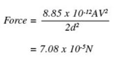
How large are the forces that are involved? Manufacturers generally don t discuss design details in depth, but if you assume an area of 0.04 mm2 (0.2 x 0.2) for each of the actuator plates, 100-V actuating voltage, and a 5- m separation, a reasonable force estimate can be made.
Electrostatic forces are at work on the plates of capacitors in the electronic devices we use each day. Of course, capacitor plates generally don t move, but they still experience forces because of the electrical field between them. For a simple parallel plate capacitor with air or vacuum between the plates
where: A = the area of either plate in m2
d = the distance in meter between the plates
V = the voltage difference between the plates
To put this into perspective, tissue paper has a mass of about 18 grams/m2 or a weight of 7 x 10⁻⁵ N per 400 mm2 area.
This force is balanced by the spring force of the moving contact support. If the applied voltage is large enough for the Coulomb force to overcome the spring force, the contacts begin moving toward each other. However, as they do, the plate separation reduces, causing the force to increase. This process progresses quickly, causing the movable contact to snap down to the fixed contact.
The problem now becomes one of making sure the moving contact support spring is strong enough to overcome stiction when the actuating voltage is removed. Early relay designs erred on the side of lower actuating voltages to improve compatibility with other circuitry. However, for some of these designs, the restoring spring force was only marginally sufficient to overcome stiction, and reliability in real-life applications was poor.
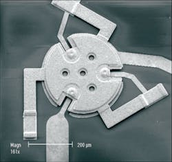
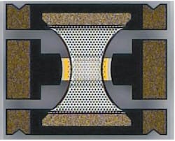
Product ExamplesTeraVictaThe calculated 7 x 10⁻⁵ N force is only a rough estimate. Adding a dielectric in the gap between the plates will increase the force generated. Also, it should be made clear that the capacitance of the actuation mechanism is very different from the capacitance of the switched contacts. This can be seen clearly in Figure 2, a photomicrograph of the patented high force disk actuator used in many TeraVicta switches.
Figure 2. Photo of a High-Force Disk Actuator Relay
Courtesy of TeraVicta The large disk measures a bit over 300 m in diameter so for the assumed 5- m gap, it would provide about twice the calculated force with a 100-V drive signal. TeraVicta specifies a maximum 70-V drive, canceling the gain in force due to area and leaving the original 7 x 10⁻⁵ N estimate.
The capacitance of a parallel plate capacitor is given by
or C = 0.13 pF for the disk actuator with a 5- m separation. Because capacitance directly relates to area, the capacitance of the contacts is very much smaller. It's difficult to scale the contact area from the figure, but assuming a 50- m dia for the slightly domed contacts, the capacitance is a factor of 36 smaller than that of the actuator or about 3.5 fF.
Making this estimate gives an idea of the off-state capacitance of the switch. TeraVicta quotes the isolation of an open switch at 31 dB up to 1 GHz, which implies a capacitance of about 2.5 fF. On the other hand, a maximum 43-dB isolation figure also is stated, corresponding to about 0.17 fF. So it's reasonable to assume an off-state capacitance of only a few fF for this switch whether based on its physical size or electrical specification.
Insertion loss is the other major specification quoted for switches and relays. It's a measure of the amount of power lost from input to output and, for the TeraVicta switches, is 0.08 dB maximum up to 1 GHz. The company reports a total contact and interconnection on-state resistance of about 0.32 Ω However, some loss also is due to shunt capacitance and series inductance, and these effects contribute to an increase in insertion loss at higher frequencies.
XCOM Wireless
Currently, XCOM is ramping up the availability of the type XW-3100 SPDT relay. Select customers are using it now, but the company's goal is for the relay to become a high-volume commercial product. Applications that can benefit most from using such a small device include ATE testhead switching.
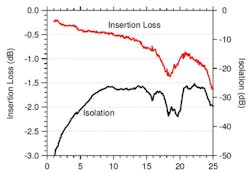
Dave DeRoo, vice president of product development at XCOM, said this relay is aimed at higher frequency switching up to at least 20 GHz. In common with other MEMS developers, he stressed the importance of packaging. Not only are the devices very small, they have critical electrical parameters as well. Providing a robust, protective package is of no use if it compromises the insertion loss or linearity, for example. Typical insertion loss and isolation curves are shown in Figure 3.
Figure 3. Typical Insertion Loss and Isolation for XW-3100 Relay
Courtesy of XCOM Wireless
Although the forces involved in MEMS relays are small, so too are the contact areas. Mr. DeRoo commented that in the XW-3100, gold contacts were used because the contact pressure was much smaller than
in conventional relays. Viewed from the perspective of Figure 1, lower pressure helps prevent contact degradation, but with silver and silver oxide contacts that are used in much larger relays, it would result in higher on-resistance.
Good, low-resistance contacts are necessary for both the TeraVicta and XCOM relays given their continuous current ratings. These relays may be small, but they are tough. TeraVicta specifies 15-W continuous RF power, which for a 50-Ω system translates to 550 mA. XCOM quotes continuous RF current as 400 mA.
Radant MEMS Radant has been developing a switch for five or six years, primarily with DARPA and military funding and with phased array radar in mind. The switches have been used by select customers for approximately two years. Recently, a large number of Radant switches were part of a successful phased array radar demonstration.In this application, individual elements of the antenna are steered electrically by altering their phase. Although such antennas were feasible in the past, MEMS relays can be integrated with the phase-shifting MMIC to improve performance and reduce size and weight. Also, the additional biasing and control circuitry required for other types of switching are reduced or eliminated.
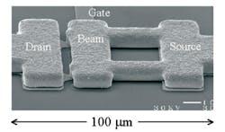
This switch is considerably smaller than the TeraVicta structure, being only 100- m long overall. It has the form of a classical cantilevered beam and requires from 40 V to 120 V for actuation. FET terminal names are used, the drain and source being input/output and the gate the control element
(Figure 4).
Figure 4. Photo of Cantilever Beam Ohmic Switch
Courtesy of Radant MEMS
According to details in a paper by J. Maciel et al of Radant, A Packaged, High-Lifetime Ohmic MEMS RF Switch, “The contact material is a thin layer of a platinum group alloy deposited on the underside of the beam and on the drain .Devices are usually operated at a contact force of 200 N and have a single contact resistance of 3 Ω. Switches typically have four to eight contacts in parallel to yield a total on-resistance of less than 1 Ω at DC and low frequencies.”
MEMtronics
In contrast to other devices that have Ohmic contacts, the MEMtronics switch is capacitive. Although the contacts may touch, only a capacitive RF shunt path to ground exists when the switch is activated. Charles Goldsmith, the company's president, said that switch characterization was progressing well with an emphasis on pull-in and release voltage as well as capacitance ratio measurement. These parameters are key to achieving high performance and reliability.
Figure 5. Photo of a Capacitive Shunt Switch
Courtesy of MEMtronics
When the switch is off with the bridge in the undeflected up position, the capacitance to either stripline is 30 fF to 40 fF. When the bridge is pulled down to the actuating contact, the shunt capacitance to ground increases to 1 pF for both striplines. Mr. Goldsmith explained that the DC control voltages and RF signals are simultaneously present on the switch conductors. Because the two types of signals are so far apart in frequency, there's no problem multiplexing or demultiplexing them onto the switches. Generally, resistive biasing is used rather than inductive biasing. Because so little current flows, using 20-kΩ resistors provides lower loss and higher bandwidth.
In a paper written with David Forehand, also at MEMtronics, Mr. Goldsmith described how some of the design trade-offs were evaluated. The company applied transient current spectroscopy to better understand charge trapping in the switch dielectric. A very long time constant was observed and the corresponding transient currents measured. From these parameters, an accurate model of the phenomena was developed. With it, various insulating materials could be evaluated quickly without the necessity of building complete MEMS switch devices.From the detailed test results, some guidelines emerged. First, keeping the actuating voltage as low as possible, at least less than 40 V, minimizes dielectric charging, a major component of stiction leading to unreliable operation. Second, reducing the amount of dielectric trades a lower capacitance ratio for longer life by reducing charge trapping.
A second paper described a mcro-encapsulation process used to package the switch. The applications for this shunt capacitance switch range up to 110 GHz, so packaging becomes even more critical at these very high frequencies.
A cage structure made from Si3N4 is formed above the actual switch structure. The cage has many very small holes in it through which the various processing steps to remove sacrificial layers must be performed. However, the holes are not large enough for a suitable liquid encapsulant to flow through them. In this manner, the switch is manufactured together with its low-cost packaging directly on the wafer. The packaging has been shown to contribute not more than 0.06-dB insertion loss at 35 GHz.3 SummaryTypes of actuators and packaging and contact materials aside, how many brands of MEMS relays can you buy today? If you answered one, you re right. If you re a defense contractor and answered two, you re right as well. Certainly, one or two is better than zero, and perhaps in a few months or years, the number will be three or even five, but today it's one or two.That's not to say that there aren t at least four types of relays that work reliably and probably more that we don t know about. So, expect to see these devices turning up in products for which MEMS relays and switches can make a big performance difference. The commercial application most manufacturers feature is high-frequency ATE. For the military, it's phased array radar.
Making reliable MEMS switches and relays simply is hard work. Many of the people directly involved at the companies included in this article have been researching this topic for 15 or 20 years. And, the relays starting to appear on the market are all very different.
For example, when discussing the MEMtronics capacitive switch, Mr. Goldsmith commented that he needed to stay far away from silicon at the very high frequencies where the switch is targeted because of material losses. Similarly, although all the manufacturers acknowledge the need for hermetic sealing at the wafer level, they each do it differently.
Do you see applications for MEMS relays and switches in the work you do? Why not contact the companies active in this field to discuss your requirements? And, if you do, tell us about it. This is an innovative new technology that will develop more quickly given interest from potential users.
References1. McKillop, J., Challenges in the Commercialization of MEMS Switches, Tera-Victa Technologies.2. Goldsmith, C., et al, Tailoring Capacitive Switch Technology for
Reliable Operation, MEMtronics.
3. Goldsmith, C., et al, Zero-Level
Packaging for RF MEMS Switches, MEMtronics.FOR MORE INFORMATION Innovative Micro TechnologyMEMS Foundry Capabilities www.rsleads.com/709ee-202MEMtronicsRF MEMS Switches www.rsleads.com/709ee-203Radant MEMSRMSW 220D SPDT MEMS Switch www.rsleads.com/709ee-205TeraVicta TechnologiesTT712-68CSP/ TT1214 www.rsleads.com/709ee-206XCOM WirelessDiscussion of RF MEMS Switch Status www.rsleads.com/709ee-207


