Addressing the Challenges of Legacy System Upgrades
A leading government contractor of electrical distribution and control systems retained G Systems to deliver a complete software upgrade for obsolete 30/60-kW generator test stands. The customer had already procured hardware to update the data acquisition (DAQ) capabilities and needed software to control the test stand and automate measurements since the legacy software platform was no longer being supported.
G Systems is an integrator of test and measurement automation solutions for the aerospace/defense, energy, medical, semiconductor, and telecom industries. Founded in 1990, the company offers services ranging from consulting to complete system builds.
G Systems chose National Instruments LabVIEW and TestStand to build the system upgrade architecture and new operator interface. The new software and DAQ unit provided up to 10 times faster tests and 2,000 times higher sampling resolution capability than the previous generation. TestStand test sequence automation offered increased throughput, UUT-level reporting, and configuration management, saving hours of manual operator input time. The updated test architecture enabled more information to be displayed during tests and provided more robust mil-spec measurement test setups with faster test times and measurement accuracy than the legacy system.
The primary reasons for upgrading most legacy systems are the lack of replacement equipment to maintain test stands, lack of support in maintaining software or control systems, and decreasing capability to measure or test improvements in product designs or changes to end-customer test requirements. For this particular system, a number of other benefits also yielded a higher return on investment which justified the cost of the upgrade:
• Supportable hardware and software platform for at least 10 years.
• Easily maintainable software for future test needs and configuration changes, providing the capabilities to meet changing test or design requirements, enhance test measurements for improving product quality, and reduce the cost in software support by using internal staff to maintain code.
• Higher data acquisition resolution and measurement accuracy, providing the capabilities to detect a wider range of faults and signals.
• Faster test step times and overall throughput, the results of both the measurement speed of the hardware and the signal processing speed of the software and a faster computer.
• Enhanced operator interface providing more measurement and diagnostic information during tests.
• Enhanced datalogging and reporting to replace many manual data entry steps.
Legacy System Upgrade
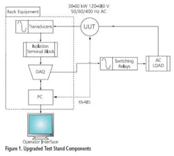
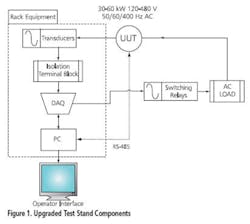
The primary change to the system hardware for the upgrade was a new USB DAQ module with 1-MHz sampling capability. This module was chosen for its easy wiring access, higher sampling rate, USB access (no spare PCI slots available in 1U rack-mount PC required by dual test head design), and low cost. Most of the transducers, switching relays, and isolation panels are still available or have equivalent replacement parts. The PC also was upgraded with a faster processor and high-speed USB ports. Figure 1 shows an overview of the hardware components.
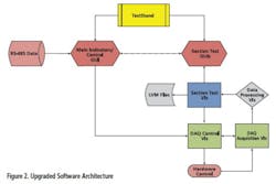
The software for replacing the system control and interface was a combination of LabVIEW and TestStand. G Systems used LabVIEW, as shown in Figure 2, for all test measurement, automation, datalogging, and operator interfaces. Figure 2 also illustrates how TestStand was used as a test executive with UUT-level reporting such as pass, fail, and limits.
DAQ Challenges and Pitfalls
There always are challenges when developing test systems. But there also are some specific things to watch for when upgrading legacy test systems, especially those involving DAQ and high power conversion. Here are some areas to pay close attention to when developing legacy system upgrades:
• Input and output signal levels of the DAQ meet or exceed existing ranges.
• System grounding and noise sources, specifically with reference to DAQ analog and digital grounds.
• Signal conditioning such as averaging, filtering, and level/frequency conversion.
• Sample rate and number of samples vs. signal processing speed—effective sampling rate.
• Ringing/decimation on adjacent DAQ channels due to the digital conversion method and varying signal-level ranges of input signals.
When upgrading a slower DAQ device to a faster rate with increased sample size, you benefit from higher resolution and the capability to capture more data. However, sometimes that benefit reveals noise in your system that previously had gone unnoticed or new artifacts from the updated hardware. It always is a good idea to have an oscilloscope and multimeter available to cross-check signals with acquired data, especially when setting up new measurement hardware and verifying signals are correctly captured.
One problem encountered with this particular upgrade was a significant amount of random spikes appearing in waveform captures that were of high enough level to cause invalid measurements. It took quite some time to figure out the source of the problem. Here are some steps to follow in isolating this kind of problem:
1. Check whether your inputs should be differential, referenced single-ended (RSE), or nonreferenced single-ended (NRSE) and verify proper wiring.
2. Trace the signal chain back to the UUT using a multimeter and an oscilloscope.
3. Measure the signal at each change in hardware or wiring, noting any differences in level, noise, and frequency.
4. Look for any repeating low-level signal that could be getting amplified through your signal chain.
5. Disconnect the UUT from the signal chain and see if noise still exists.
6. Verify that ground connections are all at the same potential. Anything over 5 Ω should be suspect as an offset from true ground. Ideally, you want shared grounds, including chassis ground, to be less than 1 Ω away from each other.
7. Check for offsets in your acquired signals that are outside the working range of your converters. This can sometimes be resolved using terminating resistors between the input and ground to pull the signal within range (experiment with resistor values typically 100 Ω to 1 k Ω).
8. If required, place an isolation signal conditioning block between the problem signal and the input. Sometimes internal components of transducers cause noise downstream.
9. Note any dramatic level changes between adjacent signal channels that could cause errors in your acquired signals due to ringing at the converters. This can be corrected by keeping similar level signals together or placing grounded channels in between. The trade-off is losing an acquisition channel.
When dealing with noise and signal quality issues, it is very easy to immediately start looking for signal conditioning blocks to solve the problem. However, these blocks can add more cost and complexity to the system and might not be needed. Don’t forget that there are significant resources available in software to address many signal processing challenges. A brief list includes averaging, windowing, and filtering.
If there is a steady noise floor above which most of the acquired signals operate or if pulses only need to be counted, for example, simply place a threshold level on the acquired data and pass only that data which is above or below depending on what is being measured. Smooth out ripple on waveforms using averaging, whether a rolling average or simple averaging, to increase test stability. Use digital filtering to remove noise or unwanted data.
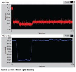
Many digital filters add some distortion to initial samples as part of their filter response. If the sample size is large enough and the signal is not varying faster than the filter response, these initial samples can be removed, giving a more stable output signal.
An example of averaging and filtering on a noisy signal is shown in Figure 3. Note the reduction in sample size from 4,000 to 3,771 samples due to filtering but that the signal being measured is much improved.
Another software-related factor to keep in mind is to ensure that any new code behaves in roughly the same manner as the legacy code and displays similar information to the operator. If not, this will lead to confusion and increase training time when switching over to the new system. Also be sure to ask the engineers and operators using the legacy system what changes would benefit the new test system. Incorporating these improvements will help in adoption of the new test system and provide higher quality software that is easier to use.
Conclusion
There are several challenges and pitfalls to avoid when upgrading legacy test systems using data acquisition. Depending on the specific test system, issues such as high-voltage signal transducers and isolation may be more prevalent than in others. But similar lessons apply across any DAQ-driven test system. Key points to remember regarding hardware are to verify that signals into the system are clean and properly grounded, the appropriate wiring setups are used for measuring signals, and signal conditioning is used as needed.
The key software points are to provide as much similarity to legacy systems as needed for operator support and to meet requirements while improving measurement quality, stability, control, and ease of use. Also, remember to thoroughly document the new code for ease of maintenance, noting any algorithms or processes used from legacy code as a starting point, and to remove as many manual processes as possible to improve system quality and increase throughput.
About the Author
Rick Garza has been a staff project engineer at G Systems since 2005. Before joining the company, he held positions as senior test engineer at Navini Networks, OEM manager at Test Technology Associates, test engineering manager at Xetel, and senior test engineer at Genrad. Mr. Garza received a B.S. Electronics Engineering Technology degree from Texas A&M University and an M.B.A. in business computer information systems from the University of North Texas. G Systems, 1240 E. Campbell Rd., Suite 100, Richardson, TX 75081, 972-234-6000, e-mail: [email protected]


