It’s obvious that over-the-air (OTA) radio transmissions go through the air and, similarly, fiber-optic communications use optical fibers. What may not be immediately apparent are the implications of the large differences between the two media.
OTA is a well-accepted acronym, but wireless signals actually propagate well in a vacuum. Generally, the atmosphere impairs radio communications, for example by absorbing microwave energy at frequencies above about 10 GHz, depending on humidity. Conversely, the ionosphere reflects short-wave signals in the 3- to 30-MHz range, enabling very long-range reception, far beyond the usual line-of-sight limitations.
Nevertheless, although radio transmissions can be reflected multiple times and suffer frequency-dependent attenuation, the medium is fundamentally linear. Signal level doesn’t cause the medium’s characteristics to change. The concept of a linear medium is important because signals only add or subtract in a linear medium.
A common linear effect in an optical fiber is dispersion, a term that refers to a frequency-dependent change in velocity. Chromatic dispersion (CD) is caused by frequency-dependent variations in a fiber’s index of refraction. The effect restricts dense wavelength division multiplexing (DWDM) to fibers having a very small CD index. Otherwise, the various wavelengths propagate at different group velocities and data reception over a long distance becomes error-prone.
On the other hand, so-called four-wave mixing (FWM) is a nonlinear effect that can occur in DWDM systems that have essentially constant phase and group velocities across the various carrier frequencies. This is important in a DWDM system with uniform carrier spacing ?f because the FWM products of mixing signals at f, f + ?f and f + 2?f are signals at f-?f, f + ?f and f + 3?f, which directly coincide with carriers already at those frequencies. A common solution is to alternate lengths of fibers with positive and negative CD or to use nonuniform frequency spacing.
FWM is one of the problems that result from the Kerr effect, an instantaneous nonlinear polarization in the medium that becomes more obvious at high power levels. Unfortunately, as more channels are used in DWDM systems and the power of each is raised to achieve greater transmission range, the increased overall power in the fiber causes larger nonlinear effects. In addition to FWM, self-phase modulation and cross-phase modulation (XPM) arise from the Kerr effect.1
Polarization mode dispersion (PMD) also affects fiber performance and is caused by imperfections in fiber symmetry. Because a signal’s polarization has both X and Y components, anything that causes a difference in propagation of either component will affect the signal’s polarization. Mechanical problems such as a tight bend radius can change PMD or the fiber itself may not be perfectly round or have completely uniform consistency throughout its length.
Because of the very large amount of information that an optical fiber can carry, especially when DWDM is used, most optical communications links operate with simple on-off keying (OOK). Either a pulse is present or it isn’t. More recently, complex modulation has been seen as a way to improve spectral efficiency, just as it has successfully done for wireless communications. The various impairments that exist in commercial networks as well as the very high symbol rates involved in complex optical modulation highlight the need for good measurement tools.
Testing Complex Fiber-Optic Modulation
Modulation Formats
Simply increasing the data rate won’t work. Higher data rates based on OOK require proportionately wider bandwidths and add noise in the same ratio. Improving the optical signal to noise ratio (OSNR) by increasing the laser power isn’t feasible and would also magnify CD and PMD effects. The present 50-GHz DWDM channel spacing limits the available bandwidth, and an important goal is to increase spectral efficiency while working with the existing fiber networks and channel spacing. The best solution is to adopt complex modulation that encodes phase and amplitude, achieving a reduced baud or symbol rate appropriate for the bandwidth.
Differential modulation formats are particularly attractive because an absolute reference isn’t required: The previous pulse becomes the reference for the current one. Differential phase shift keying (DPSK) compares the phase of the present pulse with that of the previous one. It only encodes one bit per symbol so isn’t much of an improvement over OOK.
Quadrature phase shift keying (QPSK), however, uses four phase values spaced at ?/2 intervals to encode two bits per symbol. Differential QPSK (DQPSK) has similar advantages, but the encoding is carried by the difference between successive states rather than by the states themselves. Both QPSK and DQPSK types of modulation also are used in wireless networks.
Information is associated with polarization in newer weather radar systems, but generally polarization modulation (PM) isn’t used for wireless communications. Nevertheless, in fiber-optic communications networks, it is practical to combine PM with QPSK. PM also is called dual polarization state modulation. PM-QPSK can be represented as a standard wireless QPSK phase diagram but with the two polarization states superimposed in a 3-D fashion. By encoding eight states per symbol, dual polarization QPSK (DP-QPSK) supports 100-Gb/s within a 50-GHz bandwidth.
Electrical Instruments
Several aspects of high-rate complex modulated optical signals make measurements difficult. The first is simply the high rate itself. QPSK achieves 100 Gb/s with a 25-GHz symbol rate. In practice, error correction also requires some bandwidth, so either the actual bit and symbol rates will be somewhat higher or the data rate a little less.
Although only a few QPSK systems now are being used commercially, research is under way to develop even faster schemes. Michael Schnecker, business development manager at LeCroy, described recent activity: “Our WaveMaster 830Zi DSO with 30-GHz analog bandwidth and 80-GS/s sampling rate was used by Alcatel-Lucent, Bell Labs researchers to demonstrate DP-QPSK signal transmission at 224 Gb/s, equivalent to a 56-Gbaud symbol rate. The combination of 30-GHz real-time bandwidth and the capability to emulate the coherent receiver in an intradyne system enables the detection of complex optical modulation formats such as DP-QPSK or various quadrature amplitude modulation (QAM) formats.”
For the Bell Labs experiment, four 14-Gb/s pseudo-random bit sequences (PRBS) were separately delayed and multiplexed to create I and Q 56-Gb/s bit streams. The two bit streams then drove a QPSK modulator. After splitting, one part of the signal was delayed and recombined with the other part in a polarization beamsplitter (PBS). By suitably adjusting this delay, the end result was a DP-QPSK modulated signal equivalent to a single channel rate of 224 Gb/s.
The coherent receiver is based on an intradyne technique. Heterodyne receivers mix the carrier with a local oscillator to produce an intermediate frequency (IF) higher in frequency than the bandwidth of the modulation to be recovered. With a sufficiently high IF, wide bandwidth modulation is preserved in phase and amplitude. In a homodyne receiver, the LO has exactly the same frequency as the carrier, so the modulation is recovered relative to DC. Intradyne receivers develop a relatively low-frequency IF that falls within the modulation bandwidth.
LeCroy’s Mr. Schnecker explained further, “Optical coherent receivers use an LO laser to generate a low IF because it is impractical to build an optical phase-locked loop (PLL) that would allow full heterodyne mixing as is done in RF applications. The intradyne IF is a complex signal that has a slowly varying complex center frequency causing the IQ plane to rotate at the rate of this offset.
“Once the I and Q signals are digitized in a DSO, a digital PLL recovers the bit rate, which allows the complex magnitude and phase of each symbol to be computed. The phase of a symbol is compared to the phase angle of the nearest constellation point for the given type of modulation, and the phase difference is used to correct the next symbol,” he said. “This process unwraps the phase to provide a constellation diagram from which signal errors can be measured.”
The high bandwidth and sampling rate available in Textronix DPO/DSA72000B Scopes also have proven useful in optical communications testing. According to Pavel Zivny, performance oscilloscope product engineer at Tek, “The early research simply used the scope as a raw digitizer. The DPO72004B’s combination of 20-GHz bandwidth, four channels, and 50-GS/s simultaneous sampling [made it] the only scope that could handle the multichannel signaling of 112 Gb/s on the 28-Gbaud DP-QPSK format.”
Today, several application-specific optical processing instruments have been developed that support research into even faster rates and more complex modulation schemes. In an announcement related to the 2010 OFC/NFOEC conference, Daniel van der Weide, vice president of engineering at Optametra, said, “Thanks to the flat frequency response, fast rise times, and low noise floor of Tek’s DPO72004B, we can confidently state that our OM4000 [Series of Coherent Lightwave Signal Analyzers] captures the complete electric field of the optical signal at a full 112 Gb/s.”2
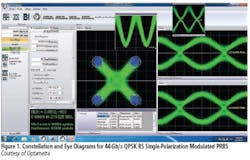
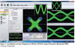
Figure 1 shows various views of 44-Gb/s QPSK return to zero (RS) single-polarization modulated PRBS analyzed by the Optametra OM4106 with a Tek DSA72004B as the digitizer. In addition to the constellation and coherently demodulated IQ eye diagrams, the inset at top center displays the output of a software-simulated delay-line interferometer (DLI) differential in-phase eye, and the inset to the right shows the power eye—the degenerate eye as it would appear on a sampling scope.
Integrated Instruments
Anritsu’s MP1800A Signal-Quality Analyzer automatically generates all the electrical, modulation, and demodulation signals required for evaluating DP-QPSK and DQPSK devices. Also, recently developed pre-code/decode software complements the instrument by supporting fully automatic generation of modulation signals needed to evaluate 100-Gb/s and 40-Gb/s optical modulation.
As explained by the company’s Hiroshi Goto, optical product specialist, “Test equipment that supports 100-Gb Ethernet (100 GE) for long distances must deal with devices that transmit and receive data using DP-QPSK modulation at a 100-Gb/s payload rate. The equipment needs to generate four synchronized 25-Gb/s serial payload streams. Similarly,” he continued, “40-Gb/s DQPSK modulation requires two synchronized 20-Gb/s streams. In both applications, the test capability must also include sufficient flexibility to allow test operators to experiment with the bit patterns and the modulation phase and frequency to determine the modulated channel’s operating margins.”
The MP1800A is specifically designed to meet the demands of ultra-high-speed physical layer tests required by 40 GE and 100 GE. The instrument offers easy-to-use software for Ethernet and SONET SDH pattern generation with an integrated pattern editor.
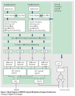
Figure 2 shows a block diagram of Agilent Technologies’ N4391A Optical Modulation Analyzer. The analyzer includes a PBS to separate the X and Y polarization components and two optical hybrids with which the I and Q components of each polarization are derived. An external LO or the tunable internal LO can be selected. In either case, the LO output is evenly split between the X and Y hybrids.
The down-converted differential X and Y IQ outputs are detected by balanced receivers and digitized. Coherent reception captures all the information about the optical signal’s electric field and allows software post-processing to minimize distortion caused by effects such as CD and PMD.
It’s important to highlight the need for real-time sampling in intradyne demodulation. High-bandwidth equivalent time sampling (ETS) scopes also have been used in optical communications research and development, but to investigate the newer high-rate complex modulation schemes, the changes from symbol to symbol must be captured in the time domain as they occur. A composite ETS view developed over many cycles of a repetitive waveform isn’t as useful.
Agilent’s Oliver Funke, photonic test and measurement product manager for the optical modulation analyzer, explained that the N4391A is a vector signal analysis solution combined with a high-speed scope. With the introduction of the 90000-X Series Scopes, four channels of 32-GHz true analog bandwidth have become available together with an 80-GS/s sampling rate. In addition, the analyzer includes a percent error vector magnitude (EVM) capability, supports user algorithms and provides in-channel CD and first-order PMD compensation.
Mr. Funke commented, “The universal receiver architecture used in the N4391A ensures that most likely only the LO laser needs to be changed to upgrade to multilevel modulation formats [such as QAM 16 or QAM 64] with tighter phase noise requirements at the receiver. The N4391A is ready to analyze these formats, thus supporting researchers working toward terabit/s optical transmission.”
JDSU’s OSA-1xx/5xx Series of Optical Spectrum Analyzer modules is a good example of this type of instrument. The basic capabilities of these analyzers are measurement of wavelength, power, and optical signal to noise ratio (OSNR) while a small resolution bandwidth allows use in systems with tight channel spacing. This series of analyzers is differentiated by insensitivity to modulation format.
The company’s Wolfgang Moench, product line manager fiber optics, explained that JDSU’s ONT-503/506/-512 Optical Network Tester 40/43 Gb/s Test Solution includes 40/43/44.6 Gb/s optical and electrical interfaces in a single instrument. Together with a commercial 43G NRZ-DPSK transponder module, the ONT-5xx makes a traffic generator and analyzer supporting complex modulation.
JDSU is a major supplier of Ethernet test tools and, when configured with the proper modules, the company’s MTS/T-BERD® and ONT platforms support Ethernet standards up to 40 GE and 100 GE. Nevertheless, because these gigabit-Ethernet standards initially are based on multiple 10-Gb/s streams and later on multiple 25-Gb/s streams, the instruments are fundamentally different from those required to capture and analyze single-stream 40- and 100-Gb/s transmissions. This format is anticipated, but likely will appear some time after an intermediate Nx25Gb/s standard. Given that many networks only now are being upgraded to 10 GE, widespread implementation of single stream 100 GE is in the future.
All-Optical Instruments
Sampling at the extremely high rates required to capture optical modulation is only just possible using the latest DSOs. Agilent and LeCroy offer the fastest combination of bandwidth and sampling rate, being about 30 GHz and 80 GS/s, respectively. Tek’s DPO/DSA72004B trails slightly in both categories. Nevertheless, none of these rates is adequate for the future, and LeCroy has recently announced extension of the company’s digital bandwidth interleave (DBI) technology to 45- and 60-GHz bandwidth. According to an April 26, 2010, press release, “This latest generation technology will use new front-end chips, which provide lower noise and higher native bandwidths. The combination of new silicon and improved DBI techniques can produce low-noise DSOs with true analog bandwidths up to 60 GHz…. The first products using this technology will be announced before the end of calendar year 2010 and will provide four simultaneous channels with 45-GHz real-time bandwidth.”
In comparison, EXFO’s PSO-100 Series Optical Sampling Oscilloscopes boast 500-GHz bandwidth and use optical sampling. FWM has been optimized in specially designed highly nonlinear fibers, and this effect generates the optical samples. Very short, high-power pulses are mixed in this fiber with the optical signal to be sampled. Because of FWM, a third carrier frequency is generated having pulses with power proportional to the original signal.
Similar to an electrical sampling scope, the actual sample rate is very much slower than the signal’s Nyquist rate and avoids the need for a fast ADC. Nevertheless, because the PSO-100 Scopes are sampling scopes, signals containing frequencies greater than half the sampling rate must be repetitive to avoid aliasing. For fast repetitive signals, the information reassembled from the optical sampling process represents a time average of the signal characteristics over a large number of cycles.
EXFO’s Francois Robitaille, senior product line manager, discussed the company’s PSO-200 Optical Modulation Analyzer, which uses a similar optical sampling technique. “The sampling technique allows true waveform recovery without any equalization. The PSO-200 provides multiple ways to view and analyze random or repetitive signals including constellation and eye diagrams and new modulation schemes such as QPSK, mQAM, DQPSK, and dual polarization transmission.”
The architecture of the PSO-200 uses the same 90° hybrid splitting technique as the Agilent block diagram shown in Figure 2. A major difference is the addition of a pulsed source input to the optical hybrid. According to the PSO-200 ordering information, you can select single or dual polarization, <20-Gbaud or >100-Gbaud transmission rate, software options such as BER analysis, and a choice of modulation formats. Also, you can choose to have or not have an LO, CD unwrapping, and digital filtering.
Conclusion
Very high-speed complex optical modulation formats certainly are going to be used in the future, and some already have been deployed. Predictably, the test equipment required at this early stage of development involves combinations of optical and electrical bench instruments. Where an integrated solution exists, it’s a general-purpose instrument rather than a compliance test set. Little emphasis on hand-held test equipment exists among manufacturers. A possible exception is optical time domain reflectometers (OTDRs) for physical fiber integrity tests.
Bandwidth and sampling rate head the list of DAQ specifications because of the high signal speeds involved. As with electrical communications signals, the choice of ETS or direct sampling is important and greatly influenced by equipment availability. The optical sampling technique supports bandwidths and equivalent sampling rates a factor of 10 greater than those of the fastest direct-sampling oscilloscopes. However, as with electrical ETS, the assembled waveform represents signal activity across a large number of cycles and cannot show what actually happened from symbol to symbol in real time.
References
1. Costa, N., and Cartaxo, A., eds. Advances in Lasers and Electro Optics, Berrettini et al, “Evolution of Optical Sampling,” April 2010, http://sciyo.com/articles/show/title/evolution-of-optical-sampling
2. http://www2.tek.com/cmswpt/prdetails.lotr?ct=PR&cs=News+Release&ci=16798&lc=EN
| FOR MORE INFORMATION | Click below | |
| Agilent Technologies | N4391A Optical Modulation Analyzer | Click here |
| Anritsu | MP1800A Signal-Quality Analyzer | Click here |
| EXFO | PSO-200 Optical Modulation Analyzer | Click here |
| JDSU | ONT-503/506/-512 Optical Network Tester | Click here |
| LeCroy | WaveMaster 830Zi DSO | Click here |
| Optametra | OM4000 Series Coherent Lightwave Signal Analyzers | Click here |
| Tektronix | DPO/DSA72004B Oscilloscope | Click here |


