Add Capacitive-Touch Technology to Your Control Design
Download this article in PDF format.
Electromechanical switches are simple, cheap, and widely available (Fig. 1). However, they’re also plagued with a number of disadvantages, including wear with repeated use, and the potential for arcing.
1. Capacitive switch technology brings many advantages, including the ability to operate in a sealed environment. (Source: TI: TIDA-00343: Low-Power Touch Through Glass Reference Design)
The last characteristic can be a serious problem in many industrial applications. In hazardous environments, for example, control switches may be part of explosion-proof controllers. These are housed in sealed metallic enclosures with thick glass windows to display local readout and programming functions. With traditional switch technology, the operator must open the enclosure to change a setting or touch a switch. This may call for special procedures and even require shutting down a process.
Technology to the rescue. A switch based on capacitive-sense technology can operate through thick glass, plastic, metal, or wood, and it can handle wet, greasy, or dirty environments without problems.
Sponsored Resources:
- Why develop with capacitive touch sensing microcontrollers?
- How can you implement capacitive touch into your design?
- What's the latest with MSP430 capacitive touch MCUs?
Basic Principles of Capacitive-Sense Technology
Capacitance is a measure of an object’s ability to store electric charge. Any two conductive materials—a wire, a PCB trace, for example—separated by an insulator will exhibit a capacitance. The proximity of an external object such as a finger may change the baseline capacitance value. This change can be measured and used to develop capacitive-sense switches, sliders, and proximity sensors.
There are two main types of capacitive-switch technology (Fig. 2). A self-capacitance, or surface-capacitance, system measures changes in capacitance with respect to earth ground. In a parallel-plate model, the electrode forms one plate of a capacitor, with the other plate being either ground or the user’s finger. A touch causes the electrode capacitance to increase, typically by 1 to 10 pF.
2. Capacitive-sense technology: A finger or other object can (a) increase or (b) decrease the base capacitance of the sensor. (Source: TI: Capacitive Sensing Basics, Figs. 5 and 7)
Self-capacitance measurement employs a single electrode and measures the change in capacitance with respect to ground caused by a typical user’s touch; the finger adds from 1 to 10 pF to the baseline measured capacitance. Any parasitic capacitances to ground in the system should be minimized as they reduce the effect of the user touch.
Self-capacitance electrodes project E-field lines in all directions as shown in Figure 2a, so interaction can occur on both sides of the electron. Ground shielding is often added to limit sensitivity to only the desired direction.
Mutual capacitance, or projected capacitance, also measures a change in capacitance (Fig. 3). In contrast to the single electrode discussed earlier, this approach uses two electrodes that together form both plates of the capacitor. The user’s finger disrupts the field between the two electrodes and reduces the coupling between the electrodes, and hence their mutual capacitance, typically by less than 1 pF.
3. A comparison of the two capacitive-sense technologies. (Source: TI: “Capacitive Touch Design Flow for MSP430 for MCUs with CapTIvate Technology” PDF)
Mutual capacitance E-fields are tightly coupled between the Tx and Rx electrodes, allowing for high-density panels. Parasitic capacitances to ground don’t affect the measurement, but the parasitic capacitance represents an additional load that affects the ability of the electrode driver electronics.
Practical Application of Capacitive-Sense Technology: Switch Matrix
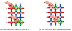
One method of creating a large keypad from a small number of pins is with an electrode matrix. Figure 4 shows a capacitive-touch matrix with four row electrodes and three column electrodes. This allows for 12 keys to be read using seven pins.
4. An electrode matrix can use either type of capacitive-sense technology. (Source: TI: Capacitive Sensing Basics, Figs. 10 and 11)
Both self-capacitance and mutual-capacitance technologies can be used. In a self-capacitance system, each row and each column is scanned as an independent electrode. Individual keys are derived by combining the data from all of the row and column electrodes to determine the position of a touch. This system has the disadvantage that multiple keys can’t be pressed simultaneously: multi-touch isn’t achievable due to “ghosting” effects.
In a mutual-capacitance design, the columns can be configured as Tx electrodes, and the rows as Rx electrodes. Every row/column intersection point then has a unique Tx/Rx combination and a unique mutual capacitance. Since each node is a unique capacitance, multiple keys can be pressed simultaneously for multi-touch operation.
Because each Rx/Tx intersection is a unique node, a controlling device could support up to 64 individual buttons in an 8 × 8 matrix configuration. Only 16 pins would need to be routed on the panel, which is easily done on a two-layer PCB. An equivalent self-capacitance design would require 64 pins, since each node would require its own I/O. Having distinct nodes also improves the reliability of the system, as each node (Rx/Tx intersection) is tracked separately in software, instead of aggregating row and column measurements to calculate the likely key press.
Which technology is best? As you expect, each one has its strengths and weaknesses. Self-capacitance designs are simpler and require less precision, but they need a higher number of input/output pins.
Mutual-capacitance measurements tend to be noisier than self-capacitance measurements because the change in capacitance caused by touching a mutual-capacitance electrode is smaller than that of a self-capacitance electrode. As a result, it’s difficult to construct large sliders and wheels from mutual capacitance electrodes—unless many electrodes are used. Mutual-capacitance electrodes lend themselves best to button matrices and more advanced sensors that require small node sizes and high electrode density.
CapTIvate Technology Simplifies the Design Process
Texas Instruments’ proprietary CapTIvate touch technology supports concurrent self-capacitance and mutual-capacitance electrodes on the same design for maximum flexibility.
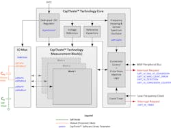
CapTIvate includes an MCU peripheral (the CapTIvate peripheral block) with two main sections: the capacitance measurement block and the digital function block. These are shown in Figure 5 as the CapTIvate Technology Measurement Block (with I/O Mux), and the CapTIvate Technology Core, respectively. There can be up to 12 measurement blocks and up to eight measurement inputs per block, depending on configuration.
5. The CapTIvate peripheral block includes both analog and digital components. (Source: TI: CapTIvate Technology Guide—Technology, Fig. 4)
The number of blocks determines the number of measurements that can be made in parallel. The number of pins per block will set the number of I/O available for a capacitive-touch measurement. A device with four blocks and four pins per block, for example, can measure four elements in parallel and provide 16 I/O. The digital block enables complementary functions: low-power operation, electromagnetic compatibility (EMC) control, and more.
Overview of the CapTIvate Sequence
Charge transfer is an effective way to measure the change of an unknown variable capacitance. The method uses periodic ratiometric measurements to compare the value of the variable electrode capacitance to that of a known, fixed capacitance. Then it can determine whether the value of the variable capacitance has changed (due to the presence of a finger, say) without knowing its absolute value.
The measurement requires a charge phase followed by a transfer phase, but the CapTIvate procedure is slightly different depending on whether the system is performing a self-capacitance or a mutual-capacitance measurement. Figure 6 shows the different implementations.
6. Both self-capacitance and mutual-capacitance measurements require charge and transfer phase, but differ in the details. Source: TI: CapTIvate Technology Guide—Technology, Figs, 2 and 3)
For self-capacitance, charge is transferred between three difference capacitors in three operations, as shown in Figure 6a:
- The Vreg capacitor (a recommended value is 1 uF) charges the external unknown variable capacitance through S2.
- S2 opens and S1 closes. The charge from the external capacitance is transferred to an internal sampling capacitor through S1b. During this transfer phase, the Vreg capacitor is recharged by a low-dropout regulator (LDO) via S1a.
- The charge and transfer phases are repeated until the voltage on the internal sampling capacitor changes by the desired amount.
During the charge phase of mutual-capacitive measurement (Fig. 6b), a sample-and-hold circuit drives the Rx node while the Tx node is pulled to ground. In the transfer phase, the Tx node is pulled high by Vreg and the charge across the capacitance is transferred to the sample capacitor.
About the MSP430 CapTIvate MCU Family
The CapTIvate peripheral block is included in several devices in TI’s MSP430 family of microcontrollers (MCUs). The MSP430 portfolio includes devices with different sets of peripherals targeted for various applications, including general-purpose, flow sensing, and capacitive touch sensing. The core architecture, combined with extensive low-power modes, is optimized to achieve extended battery life in portable measurement applications.
The MCU features a 16-bit RISC CPU, 16-bit registers, and constant generators for maximum code efficiency. The digitally controlled oscillator (DCO) allows the MCU to transition from a low-power sleep mode to active mode in less than 10 µs (typ). All MSP430 devices feature ferroelectric random access memory (FRAM)—a non-volatile memory technology that combines fast write times with very low power consumption.
There are two generations of MSP430 CapTIvate MCUs. Both the first-generation MSP430FR25xx and second-generation MSP430FR26xx offer self-capacitance and mutual-capacitance sensing capability on the same device, as well as a hardware state machine for faster conversion processing. The newer devices feature better signal-to-noise ratio (SNR) and improved immunity from conductive noise. Figure 7 compares the two generations of devices.
7. Feature comparison between first- and second-generation MSP430 CapTIvate MCUs. (Source: TI: CapTIvate Technology Guide—Device Family)
The number of CapTIvate measurement blocks on a device determines the number of sensing electrodes that can be measured simultaneously. Devices with more blocks bring the following benefits:
- Reduced measurement time, allowing for faster scanning and faster response to touches.
- Reduced parasitic loading to neighboring electrodes when electrodes are grouped together (as is common in slider and wheel applications), allowing for improved slider linearity and positional resolution
Devices with more CapTIvate blocks offer the best performance in applications with sliders or wheels (due to the improved linearity and resolution) as well as applications with many buttons (because of the improved response time). The MSP430FR2633, MSP430FR2533, MSP430FR2632, and MSP430FR2532 feature four-channel parallel scanning for optimal linearity, resolution, and response time.
When determining the best MSP430 for a given application, the designer should consider several factors, including:
- Number of CapTIvate IOs required based on the number of sensors called for by the application.
- Number of CapTIvate measurement blocks that are needed—does the application require parallel measurement, for example?
- Memory configuration (FRAM and SRAM) required to support both the CapTIvate configuration and other application functionality.
- Device peripheral configuration—serial interfaces, timers, etc.
- Device package and pinout—determines available number of GPIOs, package size, etc.
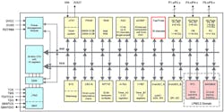
Figure 8 shows the internal block diagram of the second-generation MSP430FR2676, with more integration in the main system MCU and hardware-accelerated noise immunity post-processing. The part’s 16-kB ROM library includes CapTIvate touch libraries and driver libraries. It offers up to 64-kB program FRAM and comes in a choice of 32- 40-, and 48-pin packages that support up to 16 self-capacitive and 64 mutual-capacitive channels.
8. The MSP430FR2676 includes up to 16 CapTIvate channels. (Source: TI: MSP430FR2676 CapTIvate capacitive touch sensing microcontroller)
The CapTIvate Development Process
Developing with capacitive technology imposes its own set of requirements on product designers. For example, a capacitive-touch design requires more attention to detail from the PCB layout team than does a mechanical switch. It also requires more firmware to determine the state of the user interface.
Texas Instruments recommends following a proven development flow that provides a step-by-step procedure from initial concept to mass production. The procedure should include checklists at specific points in the flow to identify potential issues and reduce the risk of problems down the road.
A comprehensive development flow should include the following stages:
- Understand the basic principles of capacitive-touch sensing and CapTIvate technology
- Define the system requirements and product operating conditions
- Concept feasibility evaluation and device selection
- Hardware development
- Firmware development and system tuning
- System integration and prototyping
- System validation and field testing
- Mass production
Consult this application report for a comprehensive example of a development flow using the MSP430 and CapTIvate technology.
Resources for Designers
TI capacitive-touch-sensing MSP430 MCUs are supported by an extensive hardware and software ecosystem that includes reference designs, code examples, and development kits such as the MSP-CAPT-FR2633 CapTIvate Technology Development Kit. TI also provides free software, such as the CapTIvate Design Center, to help engineers quickly develop applications courtesy of an easy-to-use GUI and MSP430Ware software package Comprehensive documentation is included: The CapTIvate Technology Guide comprises an in-depth beginning-to-end review of capacitive-sense principles and technology.
There’s also a comprehensive set of reference designs that includes a touch keypad, a touch-through glass design, a proximity-sense system, and a gesture-based speaker interface, among others.
Sponsored Resources:


