Robotic Finger Digs, Finds, Identifies Small Buried Objects

What you’ll learn:
- Why and how a complicated robotic-finger design was improved by a research team.
- How this finger is used to dig into bulk materials to locate and “see” small objects.
- How the reflected image of the object is the basis for the data set that determines the actual shape of the object.
- How AI and a neural net were employed to analyze the distorted, reflected object images that were captured.
Robotic hands, fingers, grippers, and their various sensors are usually deployed to function in “free space” for many obvious reasons. But in the real world, it’s often necessary to poke and probe into materials such as sand while looking for objects like buried nails or coins (best case) or explosives (a far-worse case).
Addressing this challenge, a team at the Massachusetts Institute of Technology (MIT) has devised and tested their second-generation robotic finger specifically designed for this class of mission with impressive success: Their “Digger Finger” was able to dig through granular media such as sand and rice and correctly sense the shapes of submerged items it encountered. The objective is an electromechanical finger that replicates the capabilities of a human one, which can find, feel, and “see” (mentally) the shape of a buried object based on sensing and learned experience.
The project consists of two major aspects: the robotic finger that can penetrate into a granular mass to get close enough to illuminate and capture a reflected—albeit highly distorted—pattern, followed by artificial intelligence/neural-net data-extraction and analysis algorithms. At the core of the hardware design is GelSight, a sharp-tipped robot finger developed by researchers at MIT’s Computer Science and Artificial Intelligence Laboratory (CSAIL) (Fig. 1).
The GelSight Factor
It uses a robot finger with a small gel pad that’s pressed into objects to sense their size and texture. That’s only the data-acquisition aspect of the project, though. Another team of researchers worked to bridge the gap between touch and sight by training the system to predict what a seen object feels like and what a felt object looks like.
The GelSight arrangement uses a clear gel covered with a reflective membrane that deforms when objects are pressed against it. In the first GelSight design, three colors of LED lights and a camera are situated behind the membrane. As the LED illumination goes through the gel and onto the membrane, the camera collected the membrane’s pattern of reflection. Computer-vision algorithms then extract the 3D shape of the contact area where the soft finger touched the object.
The configuration provides an excellent sense of artificial touch, but it’s inconveniently bulky. Adding to the challenge are the realities of functioning in bulk materials, including fine-grained sand and coarse-grained rice, which have a tendency to jam the finger when numerous particles become locked in place, making it difficult to penetrate the mass.
For this improved version, the team established three goals:
- Enable the sensor to easily penetrate the granular media (as represented by both sand and rice).
- Provide improved tactile sensing to identify buried objects.
- Perform this function via a finger-like form factor so that the sensor can easily be fitted on existing robot hands.
They achieved these goals by modifying the original GelSight with respect to its sensor shape, illumination source, addition of mechanical vibration, and gel itself.
Colorful Design Details
To implement these improvements, they added a pointed tip to the earlier design (Fig. 2). They also replaced two of the color LEDs (green and red) with fluorescent acrylic paint that allows for a simple and compact design, especially at the tip (which endures the brunt of digging).
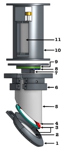
“That saved a lot of complexity and space,” said Harvard University PhD student Nancy Ouyang (Harvard works with MIT at CSAIL). “That’s how we were able to get it into such a compact form.”
Six blue-color LEDs are used to excite the fluorescent paints from the top of the Digger Finger. The final product features a device whose tactile sensing membrane is about 2 cm2, similar to the tip of a human finger.
At this point it gets complicated. To excite the red and green color paint to the required intensity, they shine an excessive amount of blue light into the Digger Finger. This, in turn, causes the image to be dominated by the blue spectrum compared to the red and green parts. To compensate, they added a small piece of yellow filter inside the lens assembly.
To address their third and fourth objectives, they mounted a high-speed micro-vibration motor (6 to 12 V, up to 18,000 rpm) on to the Digger Finger, which can “fluidize” granular media, thus clearing jams and allowing for deeper burrowing (though this fluidizing effect was harder to achieve in sand than in rice). Finally, they replaced the silicone gel of the previous GelSight sensors with a 3-mm-wide, 1.5-mm-thick double-sided, transparent polyurethane tape.
Construction of the improved Digger Finger made extensive use of 3D printing, laser cutting, and spray painting, plus building 3D-printer linkage to couple the Digger Finger to the “wrist” of the arm of the testing robot. The final Digger Finger has an outside diameter of about 22 mm.
Tests, Analysis Verify Performance
Testing the performance of this type of device represents another challenge. The group used a 12- × 12-in. crate filled about 6 inches deep with sand (density of about 1500 kg/m3) or rice (about 950 kg/m3) as the solid bulk material (Fig. 3). They used sand and rice as these have very different behaviors in the way their grains interact with the Digger Finger (they also experimented informally with washed sand, chia seeds, lentils, and mung beans).
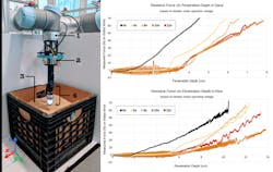
To keep the project test-phase manageable, they limited classification to four simple shapes (triangle, square, hexagon, and circle) using 3D-printed objects about 1 mm in size (Fig. 4). They ran extensive tests to measure, among other factors, the force versus achieved distance at different motor-excitation voltages. As this voltage determines both rpm and frequency, they added a 3D accelerometer to measure the vibration specifics during the test.
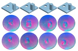
To begin the analysis, they first pressed the test objects onto the Digger Finger and collected around 1,500 usable images for each object shape. They then repeated this procedure in a container filled with sand to collect images for cases when the sand grains get stuck between the Digger Finger (sand grains distort the boundaries of the object shapes, potentially making them ambiguous).
Classification work was done by the “non-hardware” part of the team. They used a convolutional neural network (CNN), which trained a residual neural network using a machine-learning technique. This technique focuses on storing knowledge gained while solving one problem and applying it to a different but related problem.
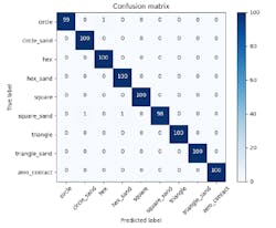
They used this pre-trained network as the starting point and then re-trained it. They split the 1,500 images into three data sets: training (1,200 images), validation (200) and testing (100). In addition, to better replicate real-world conditions, they “augmented” the training data by randomly cropping and rotating the images, as well as adding Gaussian noise. After application of the various AI/CNN tools, the result was a so-called “confusion matrix” calculated on the test images. The matrix showed validation and identification accuracy of around 98% (Fig. 5).
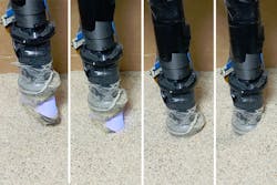
The team noted several potential impediments to proper imaging and tested various twisting motions in both the rice and sand. Sometimes, grains of each type of media would get stuck between the Digger Finger’s tactile membrane and the buried object it was trying to sense. When this happened with rice, the trapped grains were large enough to completely obscure the shape of the object, though the occlusion could usually be cleared with a little robotic wiggling.
Trapped sand was harder to clear, though the small size of the grains meant the Digger Finger could still sense the general contours of target object. The only way to come in contact with the object was to vibrate or twist the Digger Finger to push the grains to the side, with twisting to be the most efficient way of pushing rice grains to the sides.
Funding for this research was provided in part by the Toyota Research Institute through the Toyota-CSAIL Joint Research Center; the Office of Naval Research; and the Norwegian Research Council. The team plans to keep exploring new motions to optimize the Digger Finger’s ability to navigate various bulk materials. Full details are available in their highly readable paper “Digger Finger: GelSight Tactile Sensor for Object Identification Inside Granular Media.” Also, check out this mesmerizing minute-and-a-half video:
About the Author

Bill Schweber
Contributing Editor
Bill Schweber is an electronics engineer who has written three textbooks on electronic communications systems, as well as hundreds of technical articles, opinion columns, and product features. In past roles, he worked as a technical website manager for multiple topic-specific sites for EE Times, as well as both the Executive Editor and Analog Editor at EDN.
At Analog Devices Inc., Bill was in marketing communications (public relations). As a result, he has been on both sides of the technical PR function, presenting company products, stories, and messages to the media and also as the recipient of these.
Prior to the MarCom role at Analog, Bill was associate editor of their respected technical journal and worked in their product marketing and applications engineering groups. Before those roles, he was at Instron Corp., doing hands-on analog- and power-circuit design and systems integration for materials-testing machine controls.
Bill has an MSEE (Univ. of Mass) and BSEE (Columbia Univ.), is a Registered Professional Engineer, and holds an Advanced Class amateur radio license. He has also planned, written, and presented online courses on a variety of engineering topics, including MOSFET basics, ADC selection, and driving LEDs.
Comment About the Article
To join the conversation, and become an exclusive member of Electronic Design, create an account today!

Leaders relevant to this article: