Relays and Switches: Mechanical or Solid State?

Members can download this article in PDF format.
What you’ll learn:
- When to use mechanical vs. solid-state devices.
- The parameters that should be considered when selecting a device.
- Optimize your selection for lowest cost/maximum performance.
The advent of the touchscreen/capacitive sensing has many engineers wondering: Is the mechanical switch obsolete? How about the mechanical relay? There are many good reasons for using solid-state solutions, but the mechanical types still have their place and may be the right solution. The myth that mechanical devices are inherently unreliable is frequently overstated.
Just a few parameters will drive most of the decision-making regarding part selection. Learn when to choose solid state versus mechanical, and what parameters to observe when optimizing your designs for cost, reliability, and performance using mechanical variants.
Touchscreen Switches
This technology has many advantages:
- Can be made part of a sealed display.
- Easily cleaned in medical settings.
- Able to be self-labeled, which is an advantage in multi-language products.
- Infinite cycle life.
- Flexibility (software-based).
However, this technology isn’t without its flaws, which must be carefully considered given the application:
- Adds cost, requiring an LCD display/touchscreen decoding circuit/CPU with interface to decoding circuit.
- LCD display with touchscreen is ESD/EMI-sensitive, requiring protection.
- Dependent on software/firmware, adding reliability/lock-up concerns.
- Response time/only as fast as the processing firmware/submenus.
Mechanical vs. Solid State
In general, the decision to use one over the other can be reduced to balancing a few key parameters:
- Voltage/current capability/ESD
- Cost (a small MOSFET may be very inexpensive for a low-power application)
- Number of switching cycles per unit time and over its lifetime (favors solid state)
- Size of component
- Leakage in the OFF state (very important for high voltage applications, V > 60 V)
- Operating environment (temperature/humidity/dust)
- Thermal performance/Heatsinking may be necessary
Membrane/elastomeric switches are a special class of mechanical switch—to achieve their rated number of cycles requires specific printed-circuit-board plating (Au as one example). Be sure to read the datasheet so that your fabrication drawing supports such a requirement.
Derating Factors/Stress Ratio
Derating was best defined in MIL-HDBK-217 and related documents as: “Limiting the stress applied to the parts to levels that are well within their specified or proven capabilities in order to enhance their reliability.”5 I find it most useful to work with the term “Stress Ratio,” which can be defined as R = [Operating Spec/Max specified Limit].
As an example of stress ratio, R = 80% when a cap operates at 80 V, when its max limit is 100 V. Operating at 100% means that you have no margin for error and any unforeseen increases in operating point will now potentially reduce reliability. Generally, you would want to be at least at 80% or below depending how familiar you are with all of the parameters that can affect a certain specification (like operating voltage).1
The premise is that most designs are never 100% characterized or understood under all circumstances. This is the compromise between time of delivery and cost. The added margin allows for the unforeseen without undue risk to the reliability.
A safe starting point, when cost-effective, is to design for a 50% stress ratio. If the cost or other parameters aren’t within the scope of the project, adjust the ratio upwards toward 100%, but make sure the most critical parts of the system have lower stress ratios. For example, ac power switches should have a lower stress ratio than a non-critical function select switch.
Operating Temperature
Operating temperature is a key parameter that will affect the life of your product; a reduced stress level should be of prime consideration. This is especially true of solid-state switches. High temperatures accelerate oxidation and other degradation mechanisms.
A good rule of thumb to use is that for every 10°C lower max system temperature, you can double the life of the part.2 Sometimes this is accomplished by choice of location within a product, or by venting near the part. You occasionally can extend the life of the part beyond its expected life by operating it well below its maximum specified temperature.
Current Rating/Contact Material Selection
The current rating is related to the contact resistance and the heat that’s generated at the contact interface. Furthermore, the contact resistance is related to the contact force and contact material. The contact resistance goes down with more applied contact pressure.
Putting it all together, the contact resistance is usually inversely related to current rating. Achieving a high current rating requires a low contact resistance and high contact force. It’s recommended not to exceed a stress ratio of 75% on the current rating.
Because of the combinations of voltage/current ratings, and arc times, it’s illustrative to consider the following characteristics for the four key contact materials (see table). The higher the heat of vaporization, the harder it is to vaporize a contact. Values are approximate and for comparison only, as contacts are alloys rather than the pure element. It’s interesting to note that even though gold has a high melting point, its heat of vaporization is lower—one reason why gold typically isn’t used on high-voltage/high-current contacts.
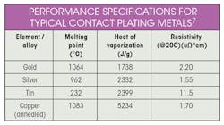
The data in this table provides some insight into why silver is a common choice for high-current contacts (low resistivity and high heat of vaporization, melting point). A characteristic of “self-healing” contributes to its high-current capacity, too.6 While copper has the highest heat of vaporization, it can also oxidize more than the other choices. Therefore, copper contacts are typically used only in high-contact force or contact wiping applications, or in higher-voltage applications (120/220-V ac applications).
Also note that the number of cycles may affect the current/power rating of a contact,3 so be sure to check for dependencies when looking up this parameter in the datasheet.
Current rating for solid-state devices is directly related to their on-resistance—how much heat it will dissipate. Typically, such devices assume a heatsink is used to achieve its maximum current rating. Be sure to consider that in your mounting scheme with an appropriate stress ratio.
There are many other specific alloys to choose from, so for more demanding applications, talk to the application engineer for the manufacturer of the part in consideration.4
# Cycles
All contacts have a finite number of connect/disconnect cycles before the contact resistance starts to rise significantly. This is another parameter that could use a healthy reduction in stress ratio as much as possible. Each design should estimate of the number of lifetime use cycles to ensure this parameter is within specification. For instance, a water sump-pump could turn on/off every hour of every day, so a switch with the following cycles is required for a five-year lifetime.
# Cycles = (1/Stress Ratio) × 24 × 365 × 5 years = 87,600 cycles required (life of five years assumed and a stress ratio of 50%; you may want to use more). In high-impedance circuits (Z > 100 kΩ) where the design could tolerate a 10X change in contact resistance (say 10 to 100 mΩ of resistance), a less aggressive stress ratio may be used (closer to 100%).
Voltage Rating
The voltage rating of a part is directly related to the spacing of the contacts, and the dielectrics that support the metal parts within the switch/relay. Exceeding the voltage rating will likely cause excessive arcing, a shortened contact life, or excessive leakage in the off state.
Since all circuits have some parasitic inductance, voltages can spike to 2X the nominal value (or more) when contacts are opened, as current can’t go instantaneously to zero in an inductor. Because of this, it’s unwise to use more than a 50% stress ratio. (Voltage rating of the contact should be 2X the operating voltage or more). This guidance is especially true for solid-state relays (SSRs). A mechanical relay can handle an occasional overvoltage state, but a SSR may not due to its semiconductor nature.
Make-Before-Break
Some contacts are set up to make the next connection span ALL of the contacts, temporarily, to avoid a completely open-circuit condition. This means that in a single-pole double-throw (SPDT) switch, three contacts of each pole will be shorted together temporarily. Select such switches/relays only if you specifically need and understand this characteristic.
Normally you would look for a “break-before-make” contact selection. Carefully check the datasheet of the part you’re using to avoid surprises when designing power circuits. Such a short may not be apparent right away, but it will cause surges in your system, likely resulting in premature failure if not anticipated.
Cost Drivers
Cost is driven by the number and complexity/size of elements of a switch or relay. The more metal you have, the more the part is going to cost. So, generally, the higher the current rating and voltage rating of the part, the bigger it will be and the more it will cost. That’s why understanding the appropriate derating factor is so critical to ensure the part is no bigger or more “powerful” than it needs to be to do its job reliably for the expected life of this part. Mastering this will ensure you haven’t under-designed it either.
The complexity of the part comes into play with a parameter such as operating speed. Sometimes you need a relay to operate quickly, and some parts are designed to do just that. However, you will pay for that added performance. Environmental capabilities also will increase cost, but if you need a relay or switch to be sealed from weather/moisture, you have no choice but to choose a component with such capability. Just check different manufacturers for the best value while considering all other parameter stress ratios.
Summary
Considering the myriad parameters, the design process can seem bewildering. So, take it step-by-step and obtain the values for the parameters listed above while applying an appropriate stress ratio. Example: If the operating voltage is 5 V, the switch you’re looking for will have a voltage rating of V = (1/stress ratio). When researching parts, it will become obvious as to which type (mechanical or solid-state) will be the better choice.
References
1. “Connector Operating Voltage, Edition 3.1.” March 2019, Fischer Connectors.
2. “Does a 10°C Increase in Temperature Really Reduce the Life of Electronics by Half?” August, 18, 2017, Ross Wilcoxon, Principal Mechanical Engineer, Rockwell Collins.
3. “Demystify Current Rating for Connector Selection,” October 1, 2002, Jensen, Eakin, Tyco Electronics.
4. “Relay Contact Life,” Doc#13C3236, TE Connectivity.
5. “Reliability Engineering for Electronic Design,” Norman B. Fuqua, Dekker Publishing, 1987.
6. “Silver: A Superior Finish for High-Current Applications,” Ed Bock, Nov. 17, 2014, APEX Electrical Interconnection Consultants.
7. MatWeb, Material Property Data.
About the Author
Mark Wagner
Senior Electrical Engineer
Mark Wagner is a 30-year industry veteran with experience in component engineering, PWB, sensor/instrumentation engineering, and low-power mixed-signal design. His experience spans commercial and military designs. Mark earned a Bachelor of Electrical Engineering at Union College, Schenectady, N.Y.
Comment About the Article
To join the conversation, and become an exclusive member of Electronic Design, create an account today!

Leaders relevant to this article: