Neutralize the Noise in Industrial RS-485 Networks

Download this article in PDF format.
The RS-485 standard defines a popular and widely used serial data interface and network that’s been in use for over 30 years. It’s found in factories, process control plants, building automation, and other industrial applications. RS-485 popularity stems from its differential transmission format that minimizes the noise inherent in most industrial settings.
Such noise tolerance and immunity is critical to the adoption of a data network for industry, as well as the selection of its cabling and transceivers. For example, a key performance characteristic for RS-485 transceivers is electrical-fast-transient (EFT) protection.
Let’s take a closer look at the RS-485 standard, and where EFT protection is achieved.
Sponsored Resources:
- What is an EFT?
- High EMC Immunity RS-485 Interface Reference Design for Absolute Encoders
- Signal Integrity vs. Transmission Rate and Cable Length for RS-485 Transceivers
A Brief Summary of RS-485
RS-485, a standard of the Electronic Industry Alliance (EIA) and the Telecommunications Industry Association (TIA), is designated as EIA/TIA-485-A. The American National Standards Institute (ANSI) also recognizes this standard. Its main features include:
- Unshielded twisted-pair (UTP) transmission line (like CAT5).
- Differential transmission.
- Mulitpoint drops or connections for up to 32 nodes.
- Half-duplex operation (single cable), full-duplex (two cables)
- Maximum range up to 5000 feet.
- Data rate depends on network length, from 100 kb/s to 50 Mb/s.
Though no formal data protocol is specified, the UART format with start and stop bits and up to 8 bits of data is commonly used, as are other proprietary protocols. Specific connectors haven’t been defined.
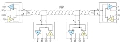
1. The RS-485 network is implemented with unshielded twisted-pair cable, such as CAT5. Up to 32 nodes can tap into the line with a transceiver. (Source: Texas Instruments)
Figure 1 shows the basic network configuration. The twisted-pair line must be terminated in its characteristic impedance (typically 120 Ω). Each node contains an IC transceiver. While the UTP balanced line is effective in canceling noise, it’s the transceiver that must provide protection, especially from extreme transients generated mainly by inductive switching commonly found in industrial settings.
What is an EFT?
An electrical fast transient is a very-high-voltage pulse or spike that occurs as the result of an inductive discharge. It’s usually produced by the switching action of inductive loads, such as a motor winding, relay, contactor, or solenoid, which are plentiful in industrial applications. The EFT generally occurs when a switching action terminates the current to an inductive load. That abrupt switching action causes the magnetic field in the inductor to quickly collapse, thereby inducing a very high voltage pulse. Remember the expression:
V = −L(di/dt)
Large inductances and rapid change in current will generate a huge voltage spike. It doesn’t last long, but it can be hundreds to thousands of volts. That current spike wreaks havoc in nearby electronic equipment. Its harmonic content is a major contributor to the overall electromagnetic interference (EMI) experienced in a factory or office building.
Such a spike will also propagate to other equipment, including any network wiring. Therefore, the transceivers on that network must be able to withstand the transients with minimal disruption to any data communications over the network. Differential cabling helps dispel the pulse, but often such a transient can kill nearby electronic circuits. That’s why certain critical circuits are protected to ensure reliable operation in a hostile, transient-heavy environment.
Transient Testing
To determine if a circuit or product can withstand an EFT, several organizations have developed testing procedures for certification purposes. For instance, the International Electrotechnical Commission’s (IEC) 61000-4-4 specification defines a form or transient pulse testing that’s used to determine the ability of a device or system to survive an EFT without damage. Various industrial or automotive certifying organizations base their testing on these testing procedures.
The testing process generates a series of high-peak-voltage pulses with fast rise times along with a rapid repetition rate. The goal is to ensure that the device or network can continue to function in the presence of high-voltage pulses without failure or to transmit data reliably without error. Other testing procedures evaluate the ability of circuits to survive various types of electrostatic discharge (ESD).
One device that has survived such rigorous testing is Texas Instruments’ THVD1550 RS-485 transceiver. It’s part of a family of RS-485 transceivers with built-in protection circuits that allow them to hold up under a barrage of IEC test procedures, including:
- ±30-kV HBM (human body model) ESD
- ±18-kV IEC 6000-4-2 ESD contact discharge
- ±25-kV IEC 6000-4-2 ESD air-gap discharge
- ±4-kV IEC 6000-4-4 EFT
The THVD1550 is a low-power-consumption IC that operates from a standard 5-V supply. It’s capable of data rates ranging from 500 kb/s to 50 Mb/s. Various package types and sizes are available.
High EMC Immunity RS-485 Interface Reference Design for Absolute Encoders
As a validation of the THVD1550’s ability to survive EFT and ESD, TI developed the High EMC Immunity RS-485 Interface Reference Design for Absolute Encoders. It’s representative of some systems in an industrial setting, such as CNC machine tools, robots, and a wide range of other motor-driven devices.
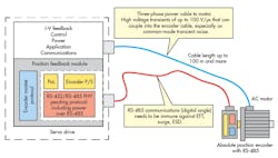
2. A typical RS-485 application is illustrated in the TI’s “High EMC Immunity Reference Design for Absolute Encoders.” Signal integrity and transient protection are essential to the system’s performance. (Source: Texas Instruments)
Figure 2 shows an example arrangement, with a servo drive unit containing the power circuitry to drive a remote ac motor. The power cable could be up to 100 meters long. Attached to the motor is an absolute position encoder that provides digital feedback to the servo-drive control circuitry. The connection is via an RS-485 bus. The RS-485 UTP cabling may run near the power bus and other sources of EMI. THVD1550 transceivers can survive any EFT or ESD disturbance that may occur.
This reference design demonstrates the use of the TI RS-485 transceivers on both the servo drive and within position encoders such as EnDat 2.2, BiSS, Tamagawa, etc. EMC immunity to inverter switching noise is particularly important for position-encoder feedback systems within industrial drives.
Signal Integrity and Transmission Rates in RS-485 Networks
As with any wired network, the data rate and error performance are a function of the cable length. The cable acts as a low-pass filter rounding pulse edges and forcing a slower bit stream. The longer the cable, the greater distortion and the lower the bit rate for a given error percentage. Ambient noise also produces jitter that affects the overall signal quality.
A key measure of signal quality is the amount of jitter that occurs. Remember that jitter is the rapid variation in time of the leading and trailing edges of a bit stream primarily caused by noise. So a longer cable generally means more noise and jitter. There are various ways to measure and express jitter. One method is to state it in terms of peak-to-peak time variation of the pulse transitions, and then express that in terms of a percentage of the transmission bit time. Eye diagrams on an oscilloscope show the jitter performance.
An application note from TI contains lab data on the signal integrity of the THVD1550 RS-485 transceiver device, at various cable lengths and data rates. Jitter measurements were gathered, with the results tabulated and plotted. For example, at 1,000 feet, the maximum data rate was 10 Mb/s with a jitter of 60 ns (43%). At 5,000 feet, the data rate maxed out at 1.5 Mb/s with a jitter of 667 ns.
Sponsored Resources:
About the Author

Lou Frenzel
Technical Contributing Editor
Lou Frenzel is a Contributing Technology Editor for Electronic Design Magazine where he writes articles and the blog Communique and other online material on the wireless, networking, and communications sectors. Lou interviews executives and engineers, attends conferences, and researches multiple areas. Lou has been writing in some capacity for ED since 2000.
Lou has 25+ years experience in the electronics industry as an engineer and manager. He has held VP level positions with Heathkit, McGraw Hill, and has 9 years of college teaching experience. Lou holds a bachelor’s degree from the University of Houston and a master’s degree from the University of Maryland. He is author of 28 books on computer and electronic subjects and lives in Bulverde, TX with his wife Joan. His website is www.loufrenzel.com.
Comment About the Article
To join the conversation, and become an exclusive member of Electronic Design, create an account today!

Leaders relevant to this article: