Download this article in PDF format.
Bandwidth consumption continues unabated for communications, security, transportation, and other applications at frequencies below about 30 GHz, which is approximately where microwave frequencies end and millimeter-wave (mmWave) frequencies begin. As a result, developers for emerging applications such as automotive radar systems, vehicle-to-vehicle (V2V) communications, and vehicle-to-everything (V2X) communications are looking to 24 GHz and beyond to find usable bandwidth with reasonable propagation distances.
Frequency spectrum is being gobbled up as fast as each new wireless application. The masses have growing appetites for wireless connectivity, including via Internet of Things (IoT) technology and in autonomous cars on smart highways in smart cities. And with bandwidth going quickly at frequencies to about 30 GHz, design engineers are turning to higher frequencies in the mmWave range.
Moving to mmWaves
Although their shorter wavelengths mean shorter propagation distances than lower-frequency signals with longer wavelengths, signals in the mmWave frequency spectrum cover wide bandwidths for short-range wireless connectivity, including for personal area networks (PANs) and high-data-rate wireless local area networks (WLANs). For example, the IEEE 802.11ad wireless gigabit (WiGig) standard is based on the use of the unlicensed 60-GHz frequency band and offers maximum data rates to 8 Gb/s at about 10 m.
Once thought experimental or reserved for military use, mmWave frequencies are increasingly finding their way into short-range communications links, medical monitoring devices, full-body security scanners, and automotive and transportation applications. Named for their short wavelengths, 10 to 1 mm for frequencies from 30 to 300 GHz, commercial mmWave devices and components typically range from about 24 to 110 GHz.
Two main application areas are expected to dominate the demand for mmWave devices and components for years to come: short-range, high-data-rate wireless communications, especially as part of 5G wireless cellular communications networks; and electronic safety systems in smart highways and autonomous vehicles and vehicles with advanced driver-assistance systems (ADAS) equipment.
Benefits of systems operating at mmWave frequencies include the small sizes of the antennas and the large available bandwidths. Among the drawbacks to using mmWave technology are the limited signal power from available ICs and discrete components, such as amplifiers, compared to components at lower frequencies, and high attenuation through atmospheric absorption and through barriers such as buildings.
The small sizes of the circuitry needed to support the small wavelengths at mmWave frequencies can also make these components more expensive to fabricate than lower-frequency components with their larger dimensions. Printed circuit boards (PCBs) for mmWave circuits require materials formulated for low loss at higher frequencies, and test equipment must have the frequency coverage and bandwidth to handle the frequency bands of interest.
To help some start at higher frequencies, Pasternack, in addition to its many mmWave components, has a 60-GHz transmit/receive development system for use in the 57- to 64-GHz V-band range. The system includes a silicon-germanium (SiGe)-based transmitter, receiver, and easy-to-use graphical user interface (GUI) that links the system to a PC by means of Universal Serial Bus (USB) cable assembly for testing IEEE 802.11ad, IEEE 802.11aj, and other network designs at V-band frequencies. The system, developed in partnership with Vubiq Networks, features a 1.8-GHz modulation bandwidth and standard WR-15 rectangular waveguide interface.
Seeking Semiconductors
Semiconductor technologies for mmWave devices range from highly integrated processes such as silicon (Si) CMOS and Si BiCMOS to “more exotic” processes like gallium arsenide (GaAs), gallium nitride (GaN), indium phosphide (InP), and SiGe. Transmitter, receiver, and transceiver ICs for mmWave applications are typically highly integrated, containing most of the components needed for mmWave radios with wide modulation bandwidths.
For example, the HMC6300 transmitter and HMC6301 receiver from Analog Devices are companion ICs that operate across the V-band frequency range from 57 to 64 GHz with a maximum modulation bandwidth of 1.8 GHz. The ICs are well-suited for 60-GHz WiGig radios and backhaul applications in 5G small cells. The devices come in compact wafer-level ball-grid-array (WLBGA) packages that integrate many different components to minimize requirements for external components in a mmWave communications link.
The HMC6300 transmitter IC features an integrated frequency synthesizer that provides tuning in 250-, 500-, or 540-MHz steps to support modulation as complex as 64QAM in unlicensed 60-GHz ISM-band applications. The transmitter is supplied in a 6- × 4-mm RoHS-compliant WLBGA. When teamed with a user’s local oscillator (LO), the transmitter chip supports frequency-shift keying (FSK), minimum-shift keying (MSK), and on-off-keying (OOK) modulation.
The model HMC6301 receiver IC also is housed in a 6- × 4-mm WLBGA. It incorporates a low-noise amplifier (LNA), image-reject filter, RF-to-IF downconverter, IF filter, I/Q downconverter, and frequency synthesizer. As with the transmitter IC, the receiver provides as much as 1.8-GHz modulation bandwidth.
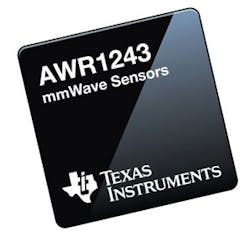
Using its low-power, 45-nm RFCMOS semiconductor process, Texas Instruments fabricates a complete single-chip FMCW transceiver for E-band frequencies from 76 to 81 GHz. Dubbed the AWR1243, it packs an integrated phase-locked loop (PLL), transmitter, receiver, and baseband circuitry in a tiny flip-chip ball-grid-array (FCBGA) package measuring just 10.7 × 10.7 mm (Fig. 1). Built with the firm’s low-power, 45-nm RFCMOS semiconductor process, the transceiver has as many as three transmit channels, four receive channels, available bandwidth to 4 GHz, and a receive noise figure of 15 dB or better.
1. This single-chip FMCW transceiver for E-band frequencies from 76 to 81 GHz is contained within an FCBGA package. (Courtesy of Texas Instruments)
The firm is well-known for automotive radar sensors based on the same semiconductor process. For example, the model AWR1443 single-chip FMCW radar sensor builds on the architecture of the AWR1243 transceiver, adding an integrated ARM R4F processor and hardware accelerator for radar data processing from 76 to 81 GHz. It also comes in a 10.7- × 10.7-mm FCBGA package for PCB mounting.
Antennas, Amplifiers, Transceivers
Anokiwave offers extensive lines of mmWave antenna ICs, from 24 GHz through around 40 GHz. As an example, its model AWA-0134 is an active antenna innovator’s kit for emerging applications at 28 GHz. Based on the company’s AWMF-0108 IC, the kit is fabricated on a surface-mount circuit board, yielding a 256-element active array that’s usable from 26.5 to 29.5 GHz with half-duplex transmit/receive operation. It can be utilized for a 256-element single beam or 4-×-64 element MU-MIMO operation with linear polarization.
Although the firm is perhaps better known for its antenna IC technology, it also produces a LNA, the AWL-7186, for E-band point-to-point communications from 71 to 85 GHz. The four-stage GaAs pHEMT amplifier provides 17-dB typical gain across its wide frequency range with better than 3.5-dB noise figure. It achieves +8 dBm output power at 1-dB gain compression and provides a 15-dB gain adjustment range.
Making use of the lower end of the mmWave frequency range, model TRX_024_006 is a transceiver IC from Silicon Radar GmbH designed for use in the 24-GHz ISM band. It integrates transmitter and receiver circuitry, including quadrature mixers, LNA, and low-phase-noise voltage-controlled oscillator (VCO), in a leadless plastic QFN20 package that measures just 3 × 3 mm2. Suitable for 24-GHz communications and radar systems, the RoHS-compliant transceiver operates from 2400 to 24.25 GHz on a single +3.3-V dc supply and consumes just 300 mW power. It includes a single-ended transmitter output and a single-ended receiver input and is fully ESD protected.
The company also supports the 24-GHz band with its model LNA_024_004 LNA in a 3- × 3-mm2 plastic QFN16 package. Covering a frequency range of 21.5 to 28.5 GHz, it has high and low gain modes, with typical gain of 15 dB in the high-gain mode and 8 dB in the low-gain mode. The noise figure is typically 5 dB with low gain and 3.2 dB with high gain. The RoHS-compliant SiGe-based LNA features low power consumption—only 18 mW from a single +3.3-V dc supply.
In support of higher data rates to and from cellular base stations, Infineon has developed a pair of single-chip transceivers for 71 to 76 GHz (model BGT70) and 81 to 86 GHz (model BGT80). The transceivers support full- and half-duplex modes with quadrature amplitude modulation (QAM) and quadrature-phase-shift-keying (QPSK) modulation formats for backhaul wireless interconnections to small cellular cell sites (such as will be used in 5G wireless networks). The transceivers provide as much as +10 dBm output power over their respective frequency bands, with receiver noise figures of 7 dB or better. Both mmWave devices come in compact embedded wafer-level ball-grid-array (eWLB) packages.
Also in the E-band frequency range, the model MAAP-011106 bare-die GaAs pHEMT amplifier from M/A-COM Technology Solutions for use from 71 to 86 GHz. It’s simply matched to 50 Ω with bond wires to a PCB and provides 20-dB small-signal gain across its frequency range. Designed to provide high-data-rate backhaul communications in point-to-point radios, the transmitter amplifier provides +25 dBm saturated output power and +30 dBm output third-order intercept point (OIP3). Each device is 100% tested.
Teledyne Scientific & Imaging and its GaAs pHEMT monolithic microwave integrated circuit (MMIC) process offers some of the industry’s highest-frequency MMICs. Using its ISO 9001:2008 certified semiconductor process, it can reliably form lithography-defined semiconductor gates with dimensions as small as 0.1 µm. Among its highest-frequency amplifiers, however, is the TO4-3S4C-G1-P1, which is fabricated on an InP substrate. The 1.92- × 0.80-mm die amplifier provides 23- to 30-dB gain from 190 to 250 GHz with typical output power of 50 to 70 mW for an input drive level of 0 dBm.
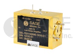
Sage Millimeter, long in the business of supplying mmWave components, offers extensive lines of high-frequency coaxial amplifiers and waveguide antennas through test equipment and other waveguide components to 325 GHz. For example, model SBL-7531142040-1010-E1 is a LNA with 20-dB gain and 4-dB noise figure from 75 to 110 GHz (Fig. 2). It’s equipped with a right-angle waveguide connector and draws 30 mA from a +8-V dc supply. The broadband amplifier is ideal for communications, imaging, and radar systems across those frequencies.
2. This LNA provides 20-dB gain and 4-dB noise figure from 75 to 110 GHz. (Courtesy of Sage Millimeter Inc.)
Millitech, part of Smiths Interconnect, maintains lines of coaxial amplifiers for mmWave applications through 110 GHz, with amplifiers available for commercial and military applications. The connector interfaces support frequency ranges from dc to 40 GHz (2.92-mm connectors), dc to 50 GHz (2.4-mm connectors), and dc to 65 GHz (1.85-mm connectors) with rectangular waveguide interfaces from WR-42 through WR-10 supplied on amplifiers for higher frequencies.
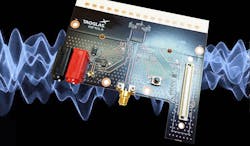
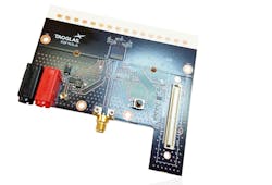
On the cusp of the mmWave frequency range, the model KSF410.A beamsteering antenna from Taoglas is a 16-element linear phased-array antenna for use from 27.50 to 28.35 GHz (Fig. 3). It provides 17-dBi gain across a 3-dB beamwidth for wide angular coverage in azimuth, with most of the energy within 45 deg. of the main beam. To save propagation losses, the beamwidth of the antenna is reduced as the antenna gain increases. The antenna has been conceived for 5G Ka-band fixed-access applications.
3. Here, a 16-element linear phased-array antenna is mounted on a PCB for use from 27.50 to 28.35 GHz. (Courtesy of Taoglas)
The KSF410.A antenna features a small-size, low-profile, and lightweight structure for ease of integration in different operating environments. Beamsteering is achieved at higher frequencies using amplitude and phase shifting or beamforming networks. Antennas within the array are organized into groups of four antenna elements, each with an IC phase shifter, LNA, and power amplifier for a wide field of view of ±45 deg.
About the Author
Jack Browne
Contributing Editor
Jack Browne, Technical Contributor, has worked in technical publishing for over 30 years. He managed the content and production of three technical journals while at the American Institute of Physics, including Medical Physics and the Journal of Vacuum Science & Technology. He has been a Publisher and Editor for Penton Media, started the firm’s Wireless Symposium & Exhibition trade show in 1993, and currently serves as Technical Contributor for that company's Microwaves & RF magazine. Browne, who holds a BS in Mathematics from City College of New York and BA degrees in English and Philosophy from Fordham University, is a member of the IEEE.


