There is no doubt that, since the introduction of USB over 20 years ago, personal computers have become easier to use. Adding a peripheral device is usually straightforward for even the most non-technical users. The simplicity of its use hides complexity in its implementation. Although an embedded software engineer need not understand every last detail of how USB works, some insight is useful, even if a commercially available USB stack is employed.
USB was invented to provide an effective and more user-friendly alternative to traditional serial and parallel interfaces. It minimises the number of connectors and cables and offers a true “plug-n-play” experience. A USB subsystem can support up to 127 devices, so it has no lack of capacity. Its performance is scalable. In its first versions, USB offered Low Speed (1.5Mb/s) and Full Speed (12Mb/s); these addressed most user requirements. USB 2.0 introduced High Speed (480Mb/s), which helped when larger quantities of data were being transferred; this applied to larger hard drives and streaming media. More recently, USB 3.x has introduced SuperSpeed (5Gb/s) and beyond.
USB Basics
There are broadly three types of device that might support USB: a “host”, which is in control of the bus (like a PC), a “function”, which is a peripheral device, like a mouse, or an “On-The-Go” device that might function as a host or a function at different times, like a digital camera.
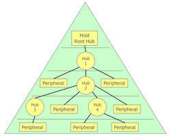
The topology of a USB system is termed a “tiered star”, with a “root hub” in the host which connects to all the USB devices, either directly or via further hubs, thus:
USB Communications
A USB peripheral controller includes a physical interface to the USB cable connector, of course, but it also incorporates a number of data buffers called “endpoints”. A device can have up to 16 numbered endpoints, each of which may contain one or two buffers (endpoint addresses), one handling data into the device and the other out. So, there are a maximum of 32 buffers. Every device must, as a minimum include Endpoint 0 with both input and output buffers.
The protocol used by USB is essentially master/slave; all communication is initiated by the host. The USB host establishes a logical connection, called a “pipe” to the endpoints on connected devices. Pipes are automatically deleted when a device is disconnected. The pipe defines the type of data transfer that may occur between that endpoint and the host.
USB Transfers
Data transmissions using USB are termed “transfers”. A transfer consists of one or more “transactions”, which, in turn, are comprised of “packets” (which may be “token”, “data” or “handshake”). Multiple transfers may be performed concurrently on a USB system, each one being interrupted to allow another to transfer some data. A transaction is an unbroken stream of data.
USB supports four types of data transfer: Control, Bulk, Interrupt and Isochronous.
Control transfers are used primarily for identification and configuration of devices, but a small data payload may also be transferred. An error correction mechanism ensures accurate transmission of data. All devices must support Control transfers and all speeds may be utilized. Control transfers are message based and, by definition, use Endpoint 0.
Bulk transfers are used by high data volume devices (like hard drives, scanners, printers etc.), where speed is desirable, but not essential, and data integrity is vital. Error correction ensures accuracy. In a Bulk transfer, data is streamed, not message based. Low Speed is not an option.
Interrupt transfers are confusingly named, because there is no means for a device to interrupt a USB host in the conventional meaning of the term. This type of transfer is used for low data volume devices (like keyboards, mice etc.). An Interrupt transfer includes error correction, can use any speed and data is streamed.
Isochronous transfers are used for very high data volume purposes (like streaming media). Such a transfer features a guaranteed delivery time, but with no error correction. Data is streamed and (of course) Low Speed is not an option.
USB Software Layers
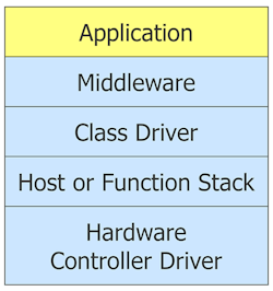
The software implementation of a USB system is necessarily quite complex and is implemented as a series of layers. Although the software for Host and Function is different – the former may be a PC, the latter is an embedded system – there is a certain symmetry in its structure:
The top layer is, of course, the application code that is utilizing USB communications.
As usual, application code is interfaced to operating system components (like USB) via middleware, such as a networking stack or file system.
A key element of a USB system is a selection of class drivers, which characterize what kind of device is being interfaced. A number of standard class drivers have been defined and may be expected to be available with any USB stack. These include: audio, communications, human interface, mass storage, still image and video. Some others are more specialized and less widely implemented, such as personal healthcare and device firmware upgrade.
If you are designing a device with a USB interface, it needs to be associated with a class driver on both ends of the bus. Although you can create a custom class driver for the function stack, it is generally considerably less work to make your device look as much like a standard as possible and, hence, make use of a supplied class driver. A strong incentive to follow this path is the requirement for a matching class driver at the host end. If you create a custom class driver for the function, you might need to also need to do more work for the host, which could include PC, Mac, Linux etc.
The Host and Function USB stacks look after the details of the USB protocols.
The bottom layer is the driver for the USB hardware controller, which takes care of the lowest level functionality.
USB and Embedded Systems
An increasing number of embedded systems incorporate USB interfaces and typically these devices are USB functions. Examples include cameras, printers, scanners, game controllers etc. To implement such software, a USB function stack is required, and this can normally be obtained from embedded software IP vendors.
Although a USB host is very commonly a desktop or laptop computer, there are occasions when an embedded system is required to behave as a host. A good example here might be a set-top box. In this case, a USB host stack is needed, which can also be obtained commercially.
Sometimes a device needs to behave both as a USB host and as a function. An example of such a requirement is a digital camera. This may behave as a function when connected to a computer to upload image files, but it will act as a host when connected to a printer to print images. To implement this functionality might require the use of both a host and a function stack. If a device is required to operate in both modes simultaneously, the dual stack approach is the only real option. However, if only one mode is required at any given time, another option may be available.
USB On-The-Go (OTG) was designed to accommodate the situation where a device might need to be a host sometimes and a function at others. It is an extension to the USB standard and includes the necessary protocols to enable the mode switch. Connectors for USB OTG are different, and it must be supported by both participating devices. It was expected that USB OTG would be very popular, but this has not yet proved to be the case.
Introduction to USB 3.0
USB 3.x is the latest iteration of the USB standard and augments the functionality and speed options of USB 2.0.
USB 3.0 incorporates the 2 wires needed to carry USB 2.0 traffic but adds a further 4 wires to carry data at higher speed. SuperSpeed is bidirectional (USB versions prior to 3.0 have all been unidirectional) and runs at 5Gb/s. SuperSpeed also accommodates higher current bus power delivery.
USB 3.0 is backwards compatible and USB 3.0 hosts and hubs support all USB 2.0 speeds. USB 2 connectors fit into USB 3.0 sockets.
USB 3.0 Speeds
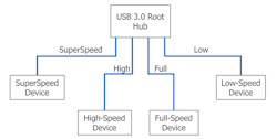
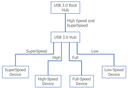
USB 3.0 supports all three speeds offered by USB 2.0 and adds SuperSpeed at 5Mb/s. A USB 3.0 hub incorporates two hubs internally: a USB 2.0 hub and a SuperSpeed hub. SuperSpeed can only be used if everything (i.e. any hubs) between a device and the host are SuperSpeed enabled. It is permissible to create a SuperSpeed device that is not functional at lower speeds, but it is required to respond to bus resets and standard resets at lower speeds.
A USB 3.0 host can communicate at the optimum speed with any USB device, thus:
A USB 3.0 hub communicates with the host using both SuperSpeed and High Speed:
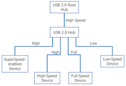
If a USB 3.0 host is connected to a USB 2.0 hub, it communicates at High Speed. This also results in communication with USB 3.0 (SuperSpeed enabled) devices downstream being at High Speed:
USB Power
It is very useful for a USB device to be able to obtain its power from the bus, instead of requiring its own power supply. The power available is a nominal 5 volts. With USB 2.0, a “High-power” device could draw up to a maximum of 500mA; a “Low-power” device could draw up to 100mA. With USB 3.0 the available current is raised to 900mA and 150mA respectively.
USB 3.1 and 3.2
Gradual enhancements have been added since USB 3.0 was introduced and these are manifest in two more incremental versions.
USB 3.1 increased the data transfer speed to 10Gb/s (SuperSpeed+). As there are two sets of signal lines, potentially 20GB/s is possible. USB 3.2 doubles this again.
More power may be delivered to devices in more flexible ways – up to 20V at 5A.
USB 3.1 also introduced the Type-C connector, which is compact, reversible (!) and has much more sophistication and flexibility, with a total of 24 pins.
USB Challenges
Deploying USB in an embedded system has challenges, both technical and commercial.
From the technical perspective, there is a challenge resulting for the sheer complexity of USB. For the software developer, much of this can be overcome by making use of a commercially available USB stack, which may be obtained from a number of vendors of embedded software IP. The remaining technical issues are largely associated with compliance and demonstrable interoperability with other USB equipment.
Commercially, the challenges are primarily financial. Most of the required information to deploy USB is freely available from the USB Implementers Forum (USB-IF). Joining the USB-IF (at a cost of approximately $4000) has a number of benefits. All USB devices need a Vendor ID and a Product ID. The assignment of a Vendor ID costs approximately $2000 (included with USB-IF membership). The owner of a Vendor ID can assign Product IDs. Certain chip vendors own Vendor IDs and will make blocks of Product IDs available to their customers at nominal or zero cost. The right to make use of one of the USB logos also attracts a fee.
Conclusions
USB has been very successful in the years since its introduction. The standard has been subject to constant revision, extension and enhancement. Some of the enhancements have been less successful: USB OTG has not been particularly popular and Wireless USB has not gained a hold at all.
USB 3.x is the latest version of the standard and brings higher speed options, improved power management and increased power availability to devices via the bus. Although new connectors are required to use the full capabilities of USB 3.x, very good backward compatibility is maintained.
