USB Type-C Boost and Buck-Boost Solutions for Programmable Power Supplies
Download this article in PDF format.
What you'll learn:
- What are the spec needs for for a USB power-sourcing programmable power supply (PPS)?
- What comprises a high-efficiency USB-C buck converter solution.
- The key factors behind a USB-C buck-boost converter solution.
Generating USB Type-C (also called USB-C) charging power for multiple peripherals requires a flexible dc-dc converter that can work with a controller to deliver the desired voltage and current capability to the corresponding device. As power density increases—particularly in multiple-power port or hub applications—efficiency becomes paramount and requires the lowest power loss to minimize internal heat. The programmable power supply (PPS) specification for USB power sourcing adds even more functionality for the power-conversion device to integrate.
This article will focus on how to implement a complete USB-C power-delivery (PD) solution with flexible functionality. The system must meet the demands of the current and voltage regulations listed in the PPS specifications, while still enabling fully functional USB Type-C products. It will cover the major aspects of design, including component selection, board layout, and functional optimization utilizing programmable features and settings.
Using the MPQ4272 boost/buck converter and MPQ4230 buck-boost converter from MPS as examples, device operation will be analyzed to optimize the switching frequency and peak current to minimize power-delivery losses. Also discussed is how to utilize a dc-dc converter with a suitable USB PD controller for a complete PD solution.
The USB PPS Specification Requirements
The PPS standard is part of the USB PD Specification (available at usb.org), and mainly focuses on facilitating fast battery charging. A PPS power source can exchange data with the powered device every 10 seconds. Therefore, the power source is able to dynamically adjust the output voltage and current according to the conditions set by the device that’s receiving the USB power.
PPS capabilities allow for small stepwise changes to be made to the voltage and current. The receiving powered device can request that the source make these changes. This power-source control is an effective way to reduce power-conversion losses, which is especially useful when a dedicated battery charger adds another level of conversion loss.
The standard process for charging a lithium-ion battery starts with a constant-current charging state (maintaining a fixed constant current while the battery voltage gradually increases). Then after reaching a specific voltage, the charging changes to constant voltage (maintaining a fixed voltage while the charge current gradually reduces). Figure 1 shows the charging profile of a Li-ion battery.
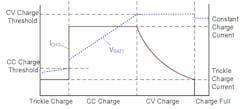
1. A lithium-ion charging profile has four charging phases: trickle charge, constant-current charge, constant-voltage charge, and charge full.
Earlier USB specifications allowed for a fixed 5-V supply voltage. USB-C PD specifications have evolved to include other higher-voltage options, but they don’t include a stepped voltage variation. The main method to charge batteries required a buck regulator-charger, which added another conversion step that generated heat and reduced efficiency.
The PPS standard allows the USB-C power source to provide voltage and current control for direct battery charging as well as reduce the power losses. The nominal step sizes for a PPS power source are 20 mV for output voltage and 50 mA for current limiting. The voltage range includes a 3.3 V minimum and a 21 V maximum.
Those ranges, coupled with USB communications protocol, enable an intelligent charging solution for single- or multi-cell battery supplies. The incremental voltage control also addresses applications where cable losses to powered devices require compensation for the I-R voltage drop to the load.
USB Power Source Solutions
The output for a USB Type-C source must adhere to output voltage and current specifications. However, the input for the source can have a variety of characteristics, such as a wide or narrow voltage range, and low to high power capabilities. Selecting a power-conversion device for the power source requires taking that input source into consideration, along with the desired output capabilities like full USB Type-C and PPS functions.
Since the maximum output voltage from the source is 21 V, a power source exceeding 21 V needs the use of a buck (also called step-down) dc-dc converter. Many applications are limited to a lower voltage, such as automotive 12-V batteries, which require using a buck-boost dc-dc converter to convert an input voltage for both higher and lower output voltages. Buck converters are normally more cost-effective due to having just two power switches versus the buck-boost’s four, although buck-boost converters are much more versatile. Figure 2 shows both solutions, which will be explored in this article.
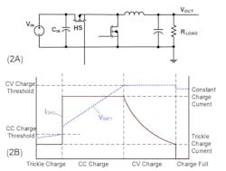
2. There are two standard USB power source solutions: buck converters (A), or step-up converters, and buck-boost converters (B), which can act as both step-up and step-down converters.
A complete USB Type-C solution needs a power-conversion component and a USB PD controller. The controller performs the necessary handshaking with the receiving power sink device, then communicates the proper setup information to the dc-dc converter to ensure that power is delivered to the USB port. An example utilizing a dc-dc converter with a controller is later on.
USB Type-C Buck Converter Solution
An ideal USB-C buck-converter solution would include high-efficiency, synchronous switching FETs, a versatile control element with built-in compensation, and a serial communications interface that provides a direct link to the USB controller device. Some devices, such as the MPQ4272 from MPS, provide these functions with a dual-output configuration for dual-port USB applications. We’ll explore this specific part as an example for buck USB Type-C solutions.
Figure 3 depicts the MPQ4272 buck converter. The device offers a maximum 36-V input voltage and load currents up to 3 A at each output, yielding a dual-output, 60-W supply solution.

3. The MPQ4272 in this example operates from a 24-V VIN, 3.3- to 21-V VOUT1/2 range, with a 3-A load.
Figure 3 shows a circuit that utilizes a 24-V input from an ac-dc wall adapter and converts to two outputs capable of a 3.3- to 21-V range suitable for PPS. The SCL and SDA signals are the I2C serial interface that access registers for general control, as well as current and voltage control. Telemetry is provided with voltage-, current-, and temperature-monitoring functions.
Figure 4 shows solution features, including line drop compensation for improved USB output voltage regulation, selectable switching frequency, and up to 98% efficiency. This high efficiency is mainly due to the power MOSFET RDS(ON) values of 2 2mΩ on the high side and 26 mΩ on the low side, which yield very low power dissipation and a case temperature rise of only 40°C with both channels powering 5-V, 3-A loads (recommended layout on 4-layer PCB).
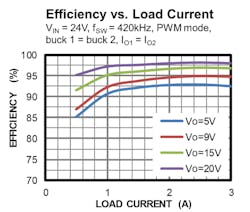
4. The MPQ4272 efficiency curve shows that an integrated solution can improve USB output voltage regulation as well as efficiency.
The output voltage control has adjustable step size and can easily meet 20 mV per step and a constant-current control mode with 50-mA steps, which is required for PPS operation.
Buck-Boost USB Type-C Solution
USB Type-C power products that use other lower-power sources—e.g., a 12-V wall adapter or a device with varying input sources—need both buck and boost dc-dc modes to produce the full 3.3- to 21-V output voltage range.
The MPQ4230 is a buck-boost solution with a maximum 36-V input voltage and four integrated switching MOSFETs to support single-inductor buck-boost conversion. It’s capable of a 3-A load current for a 20-V output, with inputs as low as 9 V.
As one example of an optimal solution, the MPQ4230 can cleanly handle switching in either buck or boost mode via the control circuitry. When the input supply voltage is close to the regulated output voltage, a special buck-boost mode is engaged, whereby all four switches are sequenced to provide effective power transfer to the load. Output constant current and voltage control includes proper step sizes for PPS operation.
Figure 5 shows the MPQ4230 powering a single USB Type-C port with USB-PD and PPS capabilities. The MPQ4230’s regulated output voltage is connected directly to the MPQ5031’s USB VBUS signal. The PD controller is the MPQ5031, a downstream-facing port (DFP) for USB provider applications. It uses the I2C serial interface to control the MPQ4230’s operation, including enabling the device, setting the output voltage and current limit, and adjusting parameters such as line drop compensation.
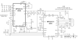
5. A 12-V VIN, 3.3- to 21-V VOUT solution for USB PD and PPS applications can regulate parameters while simultaneously allowing them to be adjusted.
Conclusion
USB single- and multi-port power products are now available with extended functionality for better control across many applications, including direct battery charging with PPS functions. Devices and solutions were presented for powering USB Type-C ports that require USB-PD and PPS functionality, which is becoming increasingly common in the latest consumer and automotive products for a variety of applications. High efficiency, full protection features, and versatile programmable functions in these types of solutions yield high-performance, cost-effective power delivery.