Supercapacitors Power Round-the-Clock Photovoltaic Lighting System

Members can download this article in PDF format.
What you'll learn:
- How to build a photovoltaic light system that operates at all times and is maintenance-free.
- The key role of the supercapacitor in this design.
- What is the "Joule Thief" circuit?
Delivering round-the-clock light, this solar photovoltaic (PV) system works for 15 years maintenance-free. Off-grid design enhances its usefulness during grid failure.
The block diagram of the system (Fig. 1) features the following:
- Solar day lamp (DL): It provides light in the daytime. It also charges the supercapacitors. These capacitors can handle daily charge/discharge cycles for years without any degradation in performance.
- Night lamp (NL): It consists of a dc-dc converter module that’s powered by the charge stored in these capacitors. The converter’s output powers two of the NL’s LEDs. The NL runs for a few hours after sunset.
- Joule Thief circuit: It extracts the residual charge from the capacitors and powers the zero lamp (ZL), which remains ON throughout the night.
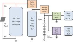
The PV panel is connected to DL1-DL6, which are LED arrays with current-limiting resistors. One other LED array, DL7, is connected to the panel through an active current-limiting circuit. Five supercapacitors are connected to DL7 through a voltage-matching circuit. This topology ensures that during low sunlight conditions, the charging of capacitors gets higher priority over the DLs.
System Design
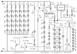
Figure 2 shows the circuit diagram of the complete system. The DL circuit in the system uses a 30-W-peak solar PV panel. The specifications of this PV panel are:
- Voltage at maximum power = Vmp = 17.7 V
- Current at maximum power = Imp = 1.7 A
The PV panel powers day lamps DL1 to DL7. The day-lamp name indicates that these lamps provide light during daytime only. All of these DLs are made up of five series-connected white LEDs having a power rating of 1 W each.
- Forward voltage drop of 1-W white LED = Vf = 3 V
- Drop across LED array = 5 * Vf = 15 V
- Residual voltage = Vmp – 15 V = 17.7 – 15 = 2.7 V
- DL current through LED array = ILED = 0.25 A (maximum permissible LED current of 0.33 A)
- Value of current-limiting resistor required = 2.7/0.25 = 10.8 Ω
- Number of DLs = Imp/ILED = 1.7/0.25 = 6.8 (rounded to seven DLs)
For DL1 to DL6, the value of resistors R1 to R6 was selected to be 10 Ω, 1 W.
Supercapacitor Charging Circuit
Capacitors C1-C5 (500 F, 2.7 V), are connected in series. The capacitor voltage is limited to 2.5 V with a 0.2-V safety margin.
Under extreme sunlight conditions, we must ensure that capacitors don’t overcharge. For this purpose, DL7 is powered using an active current-limit circuit. It consists of two PNP transistors—Q1 (BC556) and Q2 (TIP32)—and current-sensing resistor R7. Q2 is mounted on a heatsink and forward-biased using resistor R8. Q2 turns ON and current flows through the five white LEDs of DL7. When the drop across R7 exceeds Vbe of Q1, the base current of Q2 is reduced and thus limits current through DL7.
- Current limit = Vbe/R7 = 0.7/3.3 = 0.21 A
- At max current limit, the collector voltage of Q2 = Vf * 5 = 3 * 5 = 15 V
- Capacitor voltage when fully charged = Vc = 5 * 2.5 = 12.5 V
- Difference in voltage = 15 – 12.5 = 2.5 V
To compensate for this difference in voltage, capacitors are connected to the collector of Q2, through D1-D3 (1N4148) and R9 (12 Ω 1W). The current-limiting circuit ensures that voltage at the Q2 collector never exceeds 15 V at max current. (Note: To get exactly 15 V, we may have to slightly tweak the value of R7, depending on the forward characteristics of LEDs used in DL7).
Another advantage of using an active current-limiting circuit is when capacitors are fully discharged and the sunlight intensity is very low. In this case, the loop consisting of R7, Q2, D1-D3, R9, F (fuse), and C1-C5 determines the PV panel voltage. Because this voltage is much lower, DL1 to DL7 don’t turn ON. All of the available power goes to charge the capacitors. As the capacitor voltage builds up, DL1 to DL7 slowly begin to turn ON. Thus, the current-limiting circuit prioritizes the charging of capacitors when sunlight intensity is low.
With bright sunlight, all DLs will also be ON while the capacitors are being charged. Charging current is maximum when capacitors are fully discharged. As the capacitor voltage builds up, the charging current starts reducing:
- Maximum charging current of capacitors = 0.21 A (current limit)
- Minimum charging current of capacitors = (15 – 5 * 2.5 – 3 * 0.5)/12 = 0.083 A
This minimum charging current is at full sunlight intensity. A reduction in sunlight intensity reduces the charging current.
Capacitor Voltage Balancing
Supercapacitors usually have a wide tolerance in capacitance values. Therefore, each capacitor charges to a different voltage when connected in series. To balance the capacitor voltages to 2.5 V, precision shunt regulators (LM431)—IC1-IC5—are connected in parallel with each capacitor. This regulator has a precision voltage reference of 2.5 V. Hence, without any external components, just by shoring the Ref pin with the Cathode pin, it regulates the capacitor voltage to 2.5 V.
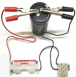
Capacitor values vary widely. So, if there are extra capacitors, it’s recommended to sort them in groups having similar capacitance values. This can be easily done by using a simple charging circuit (Fig. 3). It consists of a 1.5-V cell in series with a 100-Ω charging resistor. Connect the capacitor to the charging circuit and charge it for exactly three minutes. Note down the voltage to which it charges. Group the capacitors having same voltage (about 10% variation is OK).
With five 500-F capacitors in series, the equivalent capacitance is 100 F. If more capacitance is required, then connect two capacitors in parallel to get 1000 F each. In this case, it becomes easier to group the capacitors. Select two capacitors that have different values but when summed together, it’s close to 1000 F.
Charging duration calculations are as follows:
- Charge required to reach 12.5 V = Q = CV = 100 * 2.5 = 2500 Coulombs.
- Average charging current Ic = 0.15 A (assumed)
- Time required for charging = Q/Ic = 2500/0.15 = 16,666 sec (approx. 4 hrs)
Night Lamp
After sunset, the capacitors stop charging. The stored charge is used to turn ON night lamps NL1 and NL2. These are 1-W white LEDs connected to the output of dc-dc converter module MP1584, through R10 and R11 (3.3 Ω). Module output voltage Vdcdc is set to 3 V. The input is connected to capacitor voltage Vc. The EN pin of this module is held LOW by transistor Q3.
In the daytime, PV voltage keeps Q3 ON, through R12, LED1 (orange), and the R13 biasing circuit. After sunset, Q3 turns OFF and the EN pin goes high to turn ON NL1 and NL2. As the capacitor voltage decreases, at about 3.5 V, the module stops working and NL turns OFF.
- Current through NL1 = (Vdcdc – Vf)/R10 = (3 – 2.8)/3.3 = 0.06 A
- Power output of NL1 and NL2 = 2 * 3 * 0.06 = 0.36 W
- Input power to MP1584 = 0.36/η = 0.36/0.7 = 0.51 W
- Energy stored in capacitors = 0.5 * C *Vc *Vc = 0.5 * 100 * 12.5 * 12.5 = 7812.5 J
- Energy remaining in the capacitors = 0.5 * C * 3.5 * 3.5 = 612.5 J
- Energy consumed by NL = 7812.5 – 612.5 = 7200 J
- Run time of NL = 7200/0.51 = 14,117 sec = 3.9 hrs (approx. 3 hrs)
Joule Thief Circuit
Once NL turns OFF, the capacitors have a residual voltage of 3.5 V. Using the Joule Thief circuit, it’s possible to extract this energy down to 0.7 V. The Joule Thief is a self-oscillating voltage booster circuit.
It consists of NPN transistor Q4 (BC547C) and toroidal core transformer Tx. The primary coil of the transformer is connected between Vc and the collector of Q4. The secondary is connected to the base of Q4 with a current-limiting resistor R14 (10 kΩ).
Initially Q4 is ON, and current builds up in the primary. It induces voltage in the secondary. The secondary drives the transistor to deep saturation. Once current has built up in the primary, it stops increasing. When the rate of change of current in the primary becomes zero, there’s no voltage induced in the secondary. This turns OFF Q4. The stored energy in the primary produces a large voltage spike. The ZL (eight orange LEDs in series) connected to the collector of Q4 turns ON. Once the stored energy in the primary is transferred to LEDs, the transistor again turns ON and the cycle repeats.
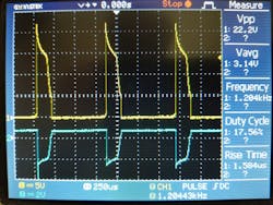
Note that, the total forward voltage of LEDs used in the ZL should be greater than Vc. In this design, Vc charges to 12.5 V. The total forward voltage of the ZL is 2 * 8 = 16 V. Figure 4 shows the Joule Thief waveforms.
Transistor Q5 also is used to sense the presence of PV voltage through D4 and R15. Throughout the day, PV voltage is available and Q5 is ON. The collector of Q5 is connected to the base of Q4. When Q5 is ON, the base of Q4 is clamped to zero voltage to keep the Joule Thief circuit in the OFF state.
Even after PV voltage becomes zero, there’s another circuit consisting of R16, D5-D7, and LED2 that still keeps Q5 ON. This is to prevent turning the Joule Thief circuit ON while NL is ON. At Vc = 3.5 V, NL turns OFF. Also, Q5 turns OFF and Q4 starts oscillating and powers ZL1.
Lastly, the circuit consisting of R17 (330 Ω, 1W) and Schottky diode D8 (1N5819) is connected from PV+ to the capacitor terminal Vc. This circuit acts as trickle charging circuit. It’s required to compensate for following losses:
- Capacitors discharge through R14 when Q5 is ON
- Quiescent current of MP1584
- Losses in R16, D5-D7, and LED2
- Current drawn by IC1-IC5 to maintain 2.5 V across each capacitor
The Zener diode ZD1 (15 V, 2 W) acts as a redundant voltage-protection circuit for capacitors. If the capacitor voltage Vc exceeds 13.5 V for any reason, then ZD1 starts conducting (the knee point of the 15-V Zener is approx. 13.5 V) Thus, it prevents the capacitor voltage Vc from exceeding its rated voltage.
Construction
The complete system is shown in Figure 5. The six DLs (DL1-DL6) are made using a metal-core PCB (MCPCB) consisting of five LEDs (a 1-W LED is actually 4 × 0.25-W LEDs in parallel). These are mounted on an aluminum channel. While sticking to the channel, a thin layer of heat-conducting paste is applied. A round 5-W MCPCB is selected for DL7. NL1 and NL2 are again made using a straight MCPCB with one LED. The ZL1 is built using eight square orange LEDs with a 20-mA current rating.
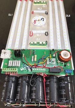
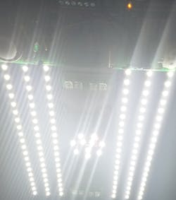
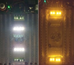
Figure 6 shows images of all the DLs turned ON during daytime. Figure 7 left photo shows the NL1 and NL2 ON after sunset (left), and ZL1 turned ON (right).
Conclusion
This day/night lamp provides light for 24 hours and runs for years on renewable energy. Being an off-grid system, it will be helpful during grid failures; it’s not exposed to voltage spikes or voltage transients. Hence, it will provide reliable service.
The cost of supercapacitors is currently on the higher side, but large-scale use of them will push the price down. The design presented here is a typical example of low-current application of supercapacitors, offering a way to reduce the cost by simplifying capacitor design to handle small charging and discharging currents. Five capacitors could be packaged in single housing with only six terminals coming out, for further cost reduction.
Reference
Electronic Design, “Solar “Day Lamp” Also Powers FM Receiver.”
About the Author
Vijay Deshpande
Dr. Vijay Deshpande worked for more than 30 years as electronics hardware engineer at various companies. He retired from Honeywell India and is now working on electronics and solar energy projects as a hobby.
Comment About the Article
To join the conversation, and become an exclusive member of Electronic Design, create an account today!

Leaders relevant to this article: