AMR Sensors: A Top Option for High-Precision Position Measurements
What you'll learn:
- What is an AMR sensor?
- How does an AMR sensor perform measurements for rotating elements?
- Making electrical and mechanical angle measurements.
The position of moving and rotating elements can be measured in many different ways. Apart from optical encoders, Hall sensors, and resolvers, magnetic sensors based on the magnetoresistive effect are used. There are giant magnetoresistive (GMR) and tunnel magnetoresistive (TMR) effects as well as an anisotropic magnetoresistive (AMR) effect, which this article delves into further.
The ADA4570 AMR sensor developed by Analog Devices (ADI) makes use of the characteristic of ferromagnetic materials whereby the electrical resistance depends on the direction of magnetization. This phenomenon was discovered by William Thomson (Lord Kelvin) around 1851:
R = R0 + ΔR × cos(2 × α) (1)
where α is the angle between the direction of magnetization and the direction of current flow.
For an optimal sensor response in linear displacement measurements, the sensor is placed such that the magnet and sensor are in the same plane and the center of the magnet is in line with the center of the sensor. Because an AMR sensor can’t distinguish between north and south poles, the position of the magnet can’t be changed.
Measuring Rotating Elements
For rotating elements, so-called off-shaft or end-of-shaft configurations are common. In the example with the off-shaft configuration (Fig. 1), the sensor sine/cosine outputs repeat the absolute information for every pole—for example, 45 degrees for a 4-pole pair magnet.
In the end-of-shaft configuration (Fig. 1, again), the sensor is situated below a rotating dipole magnet; here, the north and south poles form a uniform field above the center of the magnet. The sensor is positioned in such a way that the magnetic field and the element to be measured are in the same plane. A typical application is rotor position measurement and control in brushless dc motors.
In the case of AMR sensors, which are characteristically 180-degree angle sensors, the motor must be an even pole pair-motor; motors with an odd number of pole pairs require 360-degree information for commutation. Compared with conventional Hall sensors, which are also used in motor control, AMR sensors such as the ADA4570 and the ADA4571 have a higher precision. They also reduce the torque ripple and provide true power on absolute position information after startup or an idle state irrespective of the motor position.
Closer Look at AMR Tech
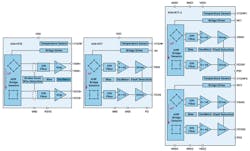
ADI’s AMR technology measures the angle by means of two Wheatstone bridges; one rotated by 45 degrees with respect to the other (Fig. 2).
The angle is calculated via sine and cosine functions and represents the orientation from 0 to 180 degrees in relation to the sensor (ADA4570):
α = arctan2 (VSIN/VCOS)/2 (2)
In AMR sensors, differentiation is made between electrical angles and mechanical angles. Due to the working principle of AMR sensors and the above-described 45-degree angle between the Wheatstone bridges, the absolute angle can be measured by means of Equation 2 over 180-degree mechanical rotation. The electrical period repeats twice over the 360-degree rotation for a dipole magnet.
Given that AMR sensors work in saturation, the absolute field strength is irrelevant, with a certain minimum magnetic-field strength present allowing for robust systems when working with strong magnets.
Apart from optical sensors, Hall sensors, and resolvers, magnetic sensors provide a further elegant solution for measuring position with high precision and robustness in many different applications. ADI offers a number of possibilities for this task, such as the ADA4570, ADA4571, and ADA4571-2 where redundancy is needed. To find out more about this topic, see the references listed below.
References
Guyol, Robert. “AN-1314 Application Note: AMR Angle Sensors.” Analog Devices, Inc., October 2014.
Nicholl, Enda. “Dual AMR Motor Position Sensor for Safety Critical Applications.” Analog Dialogue, Vol. 53, No. 4, November 2019.
About the Author
Benjamin Reiss
Field Applications Engineer, Analog Devices
Benjamin Reiss has been working at Analog Devices in Munich, Germany since April 2017. He graduated in 2016 from the Friedrich-Alexander University in Erlangen with a master’s degree in nanotechnology. After completion of the trainee program at Analog Devices, he joined the regional team as a field applications engineer supporting several broad market accounts.


