How to Design the Latest Automotive Electrical Systems

Download this article in PDF format.
The automobile is changing right before our eyes. It’s gradually morphing from a traditional internal-combustion-engine (ICE) vehicle into a hybrid electric vehicle (HEV), and then to an all-electric vehicle (EV). Next comes the fully autonomous vehicle (AV).
During these changing times, cars and trucks have evolved into significant electric/electronic platforms. Multiple electromechanical components added for safety and improved handling, including advanced driver-assistance systems (ADAS), have added to the load. Modern vehicles have also become major entertainment and communications centers—a trend that has deluged vehicles with electrical and electronic gear, pushing the 12-V electrical system to its limit. Automotive engineers are finally dealing with this problem. The solution is a 12-V plus 48-V electrical system.
Sponsored Resources:
- Why signal isolation matters in 48-V HEV/EV systems
- Current sense amplifier solutions for HEV/EV battery management systems
- Evolution of motors in 48V starter-generator systems
The 12/48-V Electrical System Overview
New and forthcoming auto electrical systems use two batteries and two power buses. Why 48 V? Mainly because higher voltage sources produce much more power (P = V2/R) to run the newer high-power auto components. Higher voltage means that current will be less for a given amount of power transferred. That translates into the ability to use smaller wiring, reducing costs and lessening the weight of the typically large wiring harnesses in vehicles today.
A simplified diagram of a dual voltage system is illustrated in Figure 1. It consists of a standard lead-acid 12-V battery typically mounted at the front of the vehicle. The second power source is a lithium-ion 48-V battery often located at the rear of the vehicle. Along with these two power sources is a significant amount of electronic circuitry that takes advantage of the multiple kilowatts of power available for distribution.
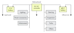
The traditional 12-V battery will continue to power the lighting, entertainment, and accessories like power windows and seats. The new 48-V segment will handle the heavier loads of power steering, engine cooling, air conditioning, active chassis systems, electro-turbo chargers, and the integrated-starter-generator (ISG) unit. The new systems have plenty of capacity for future expansion.
The ISG is an electromechanical unit that replaces the older starters and alternators. It’s designed to fit between the engine and the transmission of the newer HEV/EVs. Next-generation ISGs will probably use a brushless dc motor that requires its own electronics. The ISG unit implements the start-stop feature that many vehicles are deploying now to save fuel and minimize CO2.
The ISG restarts the engine quickly, and generates electricity when the main engine is running. In addition, it provides a measure of regenerative braking that helps recharge the 48-V battery. Essentially, starter-generator systems are at the heart of 48-V hybrid-vehicle architectures.
While a 12/48-V system is a major improvement, it relies on sophisticated electronic control circuits to manage its operation. The centerpiece of this electronics is a bidirectional dc-dc converter that can exchange power between the batteries. There will be times where one system will deliver energy to supplement the other, or so that either battery can charge the other.
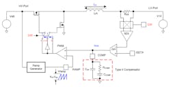
To implement the dc-dc converter, one option is to use Texas Instruments’ LM5270-Q1 IC. It’s a multiphase bidirectional current controller that permits and controls any current flow between the 12- and 48-V systems. It also provides bidirectional current regulation to 1%. Overvoltage protection is built-in, and the DIR pin controls the direction of current flow. Figure 2 shows the main circuit elements.
How Does Isolation Play into 48-V Automotive Electrical Systems?
A basic need in a dual-dc-rail power system is galvanic isolation between the two voltage systems. One obvious reason is to protect the lower-voltage circuits from possible high-voltage actions or phenomena. Most of the electronic circuits (MCU, peripheral, and interface chips) operate from 5 or 3.3 V. Any contact with 48 V would be catastrophic.
Another reason is noise on a common ground that can disrupt the operation of some equipment. However, the big problem is the even higher noise and voltage transients that can also cause damage. These transients generally come from the 48-V bus connected to the switching inverter that supplies ac to the three-phase motor generator unit. Full isolation also eliminates ground-loop problems. So, where’s the isolation?
A common arrangement is to use a transformer to couple the dc-dc converters between the 12-V bus and 48-V buses. Both half-bridge and full-bridge configurations are used. Each converter is basically an ac-dc regulator, with the transformer connecting the two systems to exchange energy.
In addition, separate isolation is required between the MCU and its control inputs. The CAN bus is widely used in automotive applications and a good choice for the new dual-voltage systems. Special electrical-isolation CAN transceiver ICs are available for this need. Isolation devices can prevent any ground loops and provide some protection from the higher-voltage system and its potential transients. In this case, you may want to consider the TI ISO1042. It provides capacitive galvanic isolation and supports a data rate to 5 Mb/s in CAN-FD mode.
The Secret to a Safe and Successful Battery and Electrical System
Vehicle electrical systems must be reliable and safe. That means careful design to ensure that failures don’t cause overheating, fires, or catastrophic failures. With two high-power battery rails and dozens of items being supplied with power, potential problems lurk in many places. One of the most dangerous components in the 12/48-V system is the lithium-ion battery.
For these reasons, these systems should be carefully monitored and protected. It involves continuously making current and voltage measurements to determine if all specifications have been met and all potentially dangerous parts of the system are protected from extreme and out-of-range values. This is accomplished by a battery-management system (BMS) and several measurement points throughout the electrical system. Voltages are easy to measure, but current and power are more difficult to measure accurately. That problem is solved with current-sense amplifiers (CSAs).
A current-sense amplifier is a specialized op amp that’s been modified and optimized for current measurements. It accomplishes this by measuring the voltage across a resistor in series with the connection to the circuit voltage source.
The CSA is configured as a differential amplifier with integrated input and feedback resistors that provide for precision gain and impedance characteristics that are essential for an accurate measurement. The CSA provides greater precision and less noise than possible with a standard op amp. The current measurement range is tens of microamps to hundreds of amps, and common-mode voltage range is −16 to +80 V. The gain error with internal resistors is as low as 0.01%.
Figure 3 shows the most common measurement configurations. The high-side configuration is popular because it can detect a load short to ground. The low-side circuit is often simpler to implement. Note that both are differential amplifiers and usually drive an analog-to-digital converter (ADC).
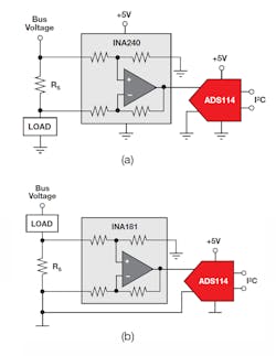
The ability to deliver accurate measurements is related to the integrated precision resistors and a precision resistor in series with the load. A typical TI model is the INA300 current-sense comparator. Others are available.
CSAs can also be connected as a fast, precise electronic fuse. This fast-acting circuit is able to disconnect the affected bus in record time—a good way to prevent damage to the multiple electronic circuits in the vehicle. TI’s TIDA 00795 reference design explains how this is accomplished.
Sponsored Resources:
About the Author

Lou Frenzel
Technical Contributing Editor
Lou Frenzel is a Contributing Technology Editor for Electronic Design Magazine where he writes articles and the blog Communique and other online material on the wireless, networking, and communications sectors. Lou interviews executives and engineers, attends conferences, and researches multiple areas. Lou has been writing in some capacity for ED since 2000.
Lou has 25+ years experience in the electronics industry as an engineer and manager. He has held VP level positions with Heathkit, McGraw Hill, and has 9 years of college teaching experience. Lou holds a bachelor’s degree from the University of Houston and a master’s degree from the University of Maryland. He is author of 28 books on computer and electronic subjects and lives in Bulverde, TX with his wife Joan. His website is www.loufrenzel.com.
Comment About the Article
To join the conversation, and become an exclusive member of Electronic Design, create an account today!

Leaders relevant to this article: