Optimize Reliability in ADAS and EV Applications with Soft Termination
Advanced driver-assistance system (ADAS) applications form one of the fastest-growing segments of automotive electronics. Stringent government regulations and consumer interest in safety applications that protect drivers and reduce accidents are fueling this rise. In parallel, government legislation and the effect of CO2 or EPA regulations are driving the industry to move away from traditional fossil fuels to electric powertrains. According to a Frost & Sullivan study released in November 2019, global sales of electric vehicles (EVs) are set to increase to about 34 million in 2025, 121.2 million in 2030, and 636.7 million by 2040.
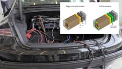
As a result of both trends, the auto industry is incorporating more multifunctional capabilities into automobiles. For example, high-power electronic control units (ECUs) support image processing for ADAS, whereas low-power ECUs are ideal for sensor and body applications. Moreover, to reduce latency in gathering data, these ECUs are now being installed in closer proximity to environmentally challenging locations, such as the engine compartment
To meet the industry’s ISO 26262 functional safety standard for automotive electronic equipment, reliability is a critical factor. ADAS applications need, more than ever, passive components that have the durability required for mechanical strength and the ability to withstand rapid temperature cycles. These include multilayer ceramic chip capacitors (MLCCs), inductors for decoupling and power-supply circuitry, and chip beads for signal and power-supply lines.
One strategy to support this requirement is to use components with resin electrodes (soft termination), which address the two common failure mechanisms: flex cracks and solder cracks.
Major Causes of Flex Cracks
Flex cracking is due to excessive circuit board flexure. This can happen during the manufacturing process, such as solder stress due to an inappropriate amount of solder, stress applied at the time of de-paneling, or screw fastening. It can also occur during final assembly and during use, stemming from exposure to continuous vibration.
MLCCs and ferrite components tend to be strong when under compression, but weak in tension. This discrepancy is due, in part, to the brittle nature of ceramics. When subjected to a tensile load, they’re unable to yield and relieve the stress, unlike metals. Thus, when a soldered component experiences excessive board flex, a crack is easily generated in the element.
A flex crack can cause the formation of an electrical conduction path between opposing internal electrodes. It’s also possible that a flex crack can propagate to a fail short condition with continued voltage and temperature cycling (Fig. 1). If a crack in a component progresses to a short-circuit failure, it may lead to problems such as heat generation, smoking, or ignition.

How to Mitigate Flex Cracks
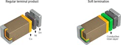
In the terminal electrode of a traditional MLCC, the copper (Cu) underlayer is electroplated with nickel (Ni) and tin (Sn). Soft termination is achieved by adding a conductive resin layer in between the Cu and Ni plating layers (Fig. 2). This resin layer acts to reduce the stresses accompanying expansion or shrinkage of the solder joints due to thermal shock or flex stress on the board, which lead to cracking of the capacitor element.
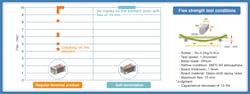
A flexure strength test comparison in Figure 3 shows the onset of cracking in the standard product at about 4 mm of deflection. In contrast, no cracking occurred in the soft-termination product even with over 10 mm of bending stress applied. Although there was peeling of the nickel layer and the conductive resin layer, cracks in the ceramic body were prevented.
Taking it one step further, in battery power lines, safety can be greatly enhanced by replacing a traditional MLCC with one that features a dual fail-safe function. MLCCs with dual safety design provide the highest protection from cracking and short-circuit occurrences. Firstly, the conductive resin is layered in the terminal electrodes, preventing crack occurrences. Secondly, the internal electrodes adopt a special structure, which is equivalent to a series-connection of two capacitors.
Such a structure will reduce the risk of short-circuiting, even if a crack does occur on the capacitor element. Moreover, since just one serial design MLCC can achieve AEC-Q200-compliant safety, instead of requiring two standard MLCCs connected in series, the parts count, PCB space, and mounting costs are cut in half.
Similarly, in the terminal electrode structure of traditional inductors and chip beads, the silver (Ag) underlayer is plated with Ni and Sn. Soft termination is achieved by applying a conductive resin layer between the Ag and Ni plating layers.
In comparison tests, multilayer inductors and chip beads—with resin electrodes—have nearly twice the board flex resistance (critical bending) of products with conventional electrodes. In traditional products, cracks developed on the ceramic element with a flex of about 4 mm. In contrast, products with soft termination can safely withstand cracking at 7 mm of flex.
Major Causes of Thermal Cracks in Solder Joints
Solder cracks occur mainly because of thermal fatigue due to thermal shock or temperature cycles and/or the use of lead-free solder, which is more brittle than lead-bearing solders. Therefore, special caution is required when mounting passive components near sources of excessive heat that may experience sudden temperature changes (thermal shock).
When thermal stress is applied repeatedly to a solder joint, the coefficient of thermal expansion (CTE) mismatch of the passive component and PCB could cause solder cracks. This can also occur when temperature control is insufficient during the soldering process.
How Soft Termination Mitigates Thermal Cracking
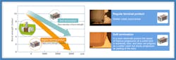
MLCCs with resin electrodes help to reduce thermal cracks in solder joints due to their outstanding thermal shock resistance (Fig. 4). In shear strength tests, a standard termination product is compared with a resin electrode product after 3,000 thermal shock cycles from −55 to +125°C. While the push strength of the conventional product decreases by approximately 90%, the soft-termination MLCCs maintain 50% of their shear strength.
The 2,000-cycle thermal shock test data of inductors and chip beads (−55 to 150°C) shows that the anchoring strength of the conventional product declined approximately 50%, as compared to around 20% for the resin electrode.
Conclusions
Mechanical stresses can produce cracking in passive components, resulting in circuit failure. Similarly, solder cracking will occur when there’s excessive stress between the board and the solder joint, causing an open circuit or the component to lose adhesion to the PCB.
Therefore, caution is required when placing components in locations that may experience significant post-solder handling stresses, such as near mounting screws, PCB edges, and corners. Additional attention should be paid to locations where extreme temperature changes (thermal cycling) occur, such as in an automobile's engine compartment. Due to the enhanced robustness of soft-termination products, the effects of board flexure and thermal shock stresses can be suppressed, improving connection reliability.
Michael Cannon is Product Manager at TDK Corporation of America.
About the Author
Michael Cannon
Product Manager, TDK Corporation of America
Michael Cannon is a product manager at TDK Corporation of America (Lincolnshire, Ill.) with over 25 years of experience across many passive component applications. He is a contributing member of the Automotive Electronics Council (AEC) and serves as the chair of the EIA Ceramic Capacitor subcommittee. Michael holds a BS in Ceramic Engineering from the University of Illinois.
Comment About the Article
To join the conversation, and become an exclusive member of Electronic Design, create an account today!

Leaders relevant to this article: