Two-Channel High-Side Switches Feature Extended Protection, Diagnostics

There seems to be no limit to the need for switches in automotive applications for both low- and high-side power control. In addition to RDS(ON), which specifies the critical parameter of on-resistance, important concerns for these devices include their various levels of protection, diagnostics, and current limiting.
Targeting this market, Rohm Semiconductor introduced a pair of similar two-channel, high-side switches for 6- to 28-V supplies. They’re not just MOSFETs—the switches comprise monolithic power-management ICs with a control unit (CMOS) and power MOSFET on a single chip: the BV2HD070EFU-C, a 70-mΩ (typical), 10-A (minimum) device; and the similar BV2HD045EFU-C, a 45-mΩ (typical), 21-A (minimum) device.
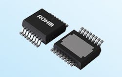
These intelligent power devices (IPDs) are housed in HSSOP-C16 packages measuring 4.90 × 6.00 × 1.70 mm (Fig. 1). The AEC-Q100-qualified (Grade 1) devices feature built-in overcurrent protection, thermal-shutdown protection, open-load detection, and undervoltage lockout functions. They also include built-in double-error flags that make it possible to distinguish between two different fault types for each channel output, and a diagnostic output function for abnormality detection. Furthermore, a user-supplied external component can arbitrarily set the value for the overcurrent limit and the time to limit to achieve the optimum tailored overcurrent protection for the load.
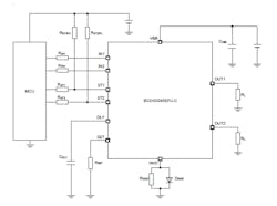
A schematic diagram of a typical application shows the handful of passive comments needed when using these devices (Fig. 2). However, that drawing on a piece of paper—or its on-screen equivalent—is only part of the design-in story.
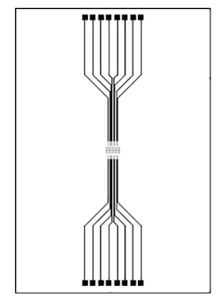
Beyond that schematic, the thermal performance in real layouts with actual circuit boards is a critical part of application analysis. As expected, the comprehensive 37-page datasheets for these devices (here for the BV2HD070EFU-C and here for the BV2HD045EFU-C) shows a basic layout footprint with track dimensions (Fig. 3), but then they go beyond that simple graphic.
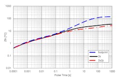
In addition to the footprint image and dimensions, the datasheets show results of transient thermal performance when using single-sided, two-sided, and four-layer FR-4 printed circuit boards (Fig. 4). Detailed tables define all relevant test-condition layout dimensions, including board area and thickness, as well as copper track width and thickness.
“These smart IPDs allow users to develop optimized solutions for resistive, inductive, and capacitive loads in automotive applications, such as automotive ECUs and vehicle cabin climate control,” said Nobuyuki Ikuta, Senior Solutions Marketing Manager at Rohm USA.
About the Author

Bill Schweber
Contributing Editor
Bill Schweber is an electronics engineer who has written three textbooks on electronic communications systems, as well as hundreds of technical articles, opinion columns, and product features. In past roles, he worked as a technical website manager for multiple topic-specific sites for EE Times, as well as both the Executive Editor and Analog Editor at EDN.
At Analog Devices Inc., Bill was in marketing communications (public relations). As a result, he has been on both sides of the technical PR function, presenting company products, stories, and messages to the media and also as the recipient of these.
Prior to the MarCom role at Analog, Bill was associate editor of their respected technical journal and worked in their product marketing and applications engineering groups. Before those roles, he was at Instron Corp., doing hands-on analog- and power-circuit design and systems integration for materials-testing machine controls.
Bill has an MSEE (Univ. of Mass) and BSEE (Columbia Univ.), is a Registered Professional Engineer, and holds an Advanced Class amateur radio license. He has also planned, written, and presented online courses on a variety of engineering topics, including MOSFET basics, ADC selection, and driving LEDs.
Comment About the Article
To join the conversation, and become an exclusive member of Electronic Design, create an account today!

Leaders relevant to this article: