Automotive ECU Inductor Touts Advances Across Multiple Parameters
It’s not easy being a passive component such as the humble inductor (also called a coil or choke, depending on how and where it’s used and fabricated). It doesn’t get much respect or attention as compared to active components and especially ICs. Still, passive components aren’t only necessary but essential, while their performance, design, and physical attributes usually have important implications for circuit performance, packaging, and manufacturability.
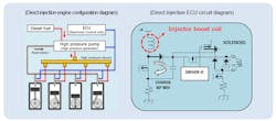
Those implications are made clear by a new inductor from Panasonic specifically targeting automotive engine control units (ECUs), which are increasingly located closer to the engine in what is a hot, vibration-intense, and generally nasty environment. The inductor in the dc-dc converter’s injector-boost circuitry must deal with high ripple currents that are always electrically and thermally stressful and challenging for long-term performance and reliability (Fig. 1).
Panasonic’s latest surface-mount automotive power chokes offer multiple benefits compared to their own predecessors:
- Cuts power loss in half (3 W versus 1.5 W) while doubling the withstand voltage from 60 V to 125 V, achieved through the use of new low-loss magnetic materials with higher withstand voltage.
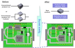
- Shrinks the size by 40% and number of coils required to be incorporated into ECUs due to the improved performance, resulting in a smaller ECU.
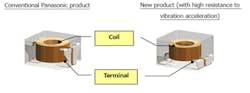
- Eliminates the need for anti-vibration reinforcement measures as part of the mounting process, such as bonding-agent adhesives. The part accomplishes this via proprietary coil-winding and -forming technologies, which reduce the height of the terminal's pull-out position (contacts) to half compared to the company's conventional products (Fig. 2). The vibration resistance jumps significantly from a modest 5 g to a more substantial 30 g while the self-resonant frequency increases from 1300 Hz to 2500 Hz.
Using this inductor, a smaller ECU implementation is feasible, again when compared to using their previous-generation product (Fig. 3).
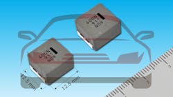
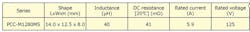
The table shows the top-tier specifications for the PCC-M1280MS, the first model in the family; other units will follow in 2021.
More information on the PCC-M1280MS and follow-on inductors, as well as construction and application insight, is available here.
About the Author

Bill Schweber
Contributing Editor
Bill Schweber is an electronics engineer who has written three textbooks on electronic communications systems, as well as hundreds of technical articles, opinion columns, and product features. In past roles, he worked as a technical website manager for multiple topic-specific sites for EE Times, as well as both the Executive Editor and Analog Editor at EDN.
At Analog Devices Inc., Bill was in marketing communications (public relations). As a result, he has been on both sides of the technical PR function, presenting company products, stories, and messages to the media and also as the recipient of these.
Prior to the MarCom role at Analog, Bill was associate editor of their respected technical journal and worked in their product marketing and applications engineering groups. Before those roles, he was at Instron Corp., doing hands-on analog- and power-circuit design and systems integration for materials-testing machine controls.
Bill has an MSEE (Univ. of Mass) and BSEE (Columbia Univ.), is a Registered Professional Engineer, and holds an Advanced Class amateur radio license. He has also planned, written, and presented online courses on a variety of engineering topics, including MOSFET basics, ADC selection, and driving LEDs.
Comment About the Article
To join the conversation, and become an exclusive member of Electronic Design, create an account today!

Leaders relevant to this article: