Magnet-Free Inductive Position Sensor Targets Automotive-Motor Commutation

Closed-loop motor control generally requires sensors that accurately determine the position of the motor rotor to effectively implement communication of the excitation for the windings (an exception is the algorithm-intensive vector/field-oriented control for three-phase ac motors). Among the sensing options are Hall-effect devices; optical, capacitive, and magnetic encoders; resolvers; and inductive sensors.
In recent years, the last-listed sensor has received more attention for a variety of reasons. If you’re not familiar with the basic operating principles of inductive position sensors, the Reference cited at the end provides a clear, crisp description along with additional insight. It explains the basic operation by pointing out:
“The label can be confusing, but the truth is, inductive sensors do not measure inductance. Instead, they use the electromagnetic induction of a magnetic field in a metal target along with the well-known properties of an air core transformer and Faraday's law to accurately locate the disturbance of this magnetic field by the target. It may sound complicated to many of us who have forgotten all we learned about electromagnetic field theory from school. Simply put, though, inductive sensors measure the disturbance of a magnetic field by a conductive target.”
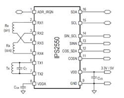
Addressing the interest in this sensing approach, the magnet-free IPS2550 IC from Renesas Electronics Corp. is an inductive position sensor designed for use with traction motors; electronic power steering; starter generators in passenger cars and heavy-duty commercial and off-road vehicles; and motorbikes (Fig. 1). It supports electrical speeds up to 600 krpm and is designed to be used around the motor as it accommodates both off-axis and on-axis positioning.
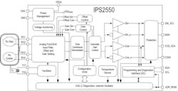
The sensor is AEC-Q100 qualified for stable operation in harsh environments over −40 to +160°C ambient temperatures, and it offers enhanced accuracy and production stability with sine/cosine gain mismatch and offset compensation. The IPS2550 has been developed according to ISO 26262 ("Road vehicles – Functional safety") requirements to support its most challenging functional safety-critical applications. Furthermore, it supports system-level requirements up to ASIL-C(D).
The digital communication interface of the IPS2550 uses I2C standard mode to program, configure, and read its diagnostic status. In addition to using the dedicated SDA and SCL pins, it can communicate via I2C protocol over the analog output pins to reduce the number of wires to a sensor module. The device includes automatic gain control (AGC) to compensate for the inevitable air-gap variations, and features overvoltage, reverse polarity, and short-circuit protection. Transmit-side bias current for this 3-V/5-V device is just 496 μA.
To support design-in, Renasas also offers an evaluation kit consisting of a communication board and an application module (Fig. 2). The communication board, which runs the IPS2550 GUI, is connected to the IPS2550 application module, and it can display the sine and cosine signals provided by the inductive position sensor.
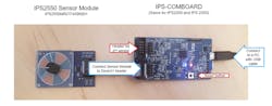
The IPS2550 application module connects to a motor and provides four periods of sine and cosine analog signals per mechanical revolution. This evaluation kit comes equipped with all of the necessary USB and flat connection cables for plug and play, and its communication board supports programming of the IPS2550 position sensor.
The IPS2550 (datasheet here), available in a TSSOP-16 package with exposed pad, is priced at $4.76 USD per unit in 1,000-unit quantities.
Reference
Electronic Design, “11 Myths About Inductive Position Sensors”
About the Author

Bill Schweber
Contributing Editor
Bill Schweber is an electronics engineer who has written three textbooks on electronic communications systems, as well as hundreds of technical articles, opinion columns, and product features. In past roles, he worked as a technical website manager for multiple topic-specific sites for EE Times, as well as both the Executive Editor and Analog Editor at EDN.
At Analog Devices Inc., Bill was in marketing communications (public relations). As a result, he has been on both sides of the technical PR function, presenting company products, stories, and messages to the media and also as the recipient of these.
Prior to the MarCom role at Analog, Bill was associate editor of their respected technical journal and worked in their product marketing and applications engineering groups. Before those roles, he was at Instron Corp., doing hands-on analog- and power-circuit design and systems integration for materials-testing machine controls.
Bill has an MSEE (Univ. of Mass) and BSEE (Columbia Univ.), is a Registered Professional Engineer, and holds an Advanced Class amateur radio license. He has also planned, written, and presented online courses on a variety of engineering topics, including MOSFET basics, ADC selection, and driving LEDs.
Comment About the Article
To join the conversation, and become an exclusive member of Electronic Design, create an account today!

Leaders relevant to this article: