IC Measures, Monitors, Manages Stacked Battery Cells

It’s one thing to provide battery management for one or a few cells. It’s a far more difficult challenge when you must do so on a series of stacked cells, due to issues of common-mode voltage (CMV), multiplexing, data time-skew, per-channel offsets and errors, and more.
Yet as batteries improve in energy density (by weight and volume), drop in cost, and offer other advantages, they’re increasingly being used in such series arrangements, with the electric vehicle (EV) being the most visible example. Other applications include electric bikes, battery-backup systems, supercapacitor-based systems, and even battery-powered tools. Although these cells are in a series configuration, it’s imperative to monitor each cell independently of the others.
Providing cell-voltage sensing in these applications is the function of the Maxim MAX17852, a 14-channel (cells), high-voltage data-acquisition system that the vendor maintains is industry’s first to reach ASIL-D compliance for voltage, current, temperature, and communication in a battery-management system (BMS) (Fig. 1). Maxim also maintains that using this AEC-Q100 Grade 1 qualified IC results in a design which is up to 16% smaller than a discrete solution and with a cost savings of up to 20%
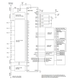
(ASIL refers to Automotive Safety Integrity Level, a risk-classification system defined by the ISO 26262 standard for the functional safety of road vehicles with four ASIL grades A, B, C, and D. ASIL A represents the lowest degree and ASIL D represents the highest degree of automotive hazard. Systems like airbags, anti-lock brakes, and power steering require an ASIL-D grade.)
The system can measure up to 14 cell voltages, one current, and a combination of four temperatures or system voltages with fully redundant measurement engines in just 263 µs, or do all inputs solely with the analog-to-digital converter (ADC) measurement engine in 156 µs. Such low time-skew channel-to-channel readings are critical to effective stack management.
For increased noise immunity, oversampling is available whereby up to 128 measurements per channel can be averaged internally with 14-bit resolution and then combined with digital post-processing IIR filtering. The 14 internal switches for cell balancing are rated at over 300 mA.
Cell and bus-bar voltages ranging from –2.5 to +5 V are measured differentially over a 65-V common-mode range with typical cell-voltage measurement accuracy of ±0.45 mV at room temperature and a maximum of ±2 mV error (5 to 40°C) and 4.5 mV (–40 to +125°C). Since many systems have more than “just” 14 cells, up to 32 devices can be daisy-chained to manage 448 cells and monitor 128 temperatures.
The MAX17852 allows both Hall-effect sensors and shunt resistors to be used as sensing components. The integrated low-noise current-sense amplifier with 5-mA resolution (at gain of 256) eliminates the need for an external component and ensures that current information is acquired at the same time as cell voltage and temperature (again, timing-skew issues). It uses Maxim’s battery-management UART or SPI protocol for robust communications and supports an I2C master interface for external device control.
As an ASIL-D device, it includes extensive monitoring and diagnostics for system performance, including overvoltage, undervoltage, undertemperature, and overtemperature conditions, as well as cell conditions such as excess temperature and even single-cell mismatch alert. The MAX17852 includes a factory-trimmed oscillator (thus, no external crystal is needed) and comes in a 64-pin (10 × 10 mm) LQFP package. It’s priced at $7.52 (1000 pieces) and is supported by an impressive 370-page datasheet that addresses performance, specifications, and operational issues in detail.
To enhance familiarity with the IC and accelerate the design-in effort, Maxim also offers the MAX17852EVKIT# evaluation kit for $250 (Fig. 2). The kit’s GUI provides for initialization, operation, and data analysis, all of which are discussed the 46-page datasheet that also includes schematics, bill of materials (BOM), and PCB layout details.
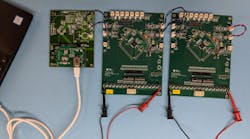
The kit features force and sense pin headers for precision measurements, and rather than require the user to use batteries at first (that can get complicated on the breadboard and at the lab bench), there’s a built-in resistor stack for battery emulation.
About the Author

Bill Schweber
Contributing Editor
Bill Schweber is an electronics engineer who has written three textbooks on electronic communications systems, as well as hundreds of technical articles, opinion columns, and product features. In past roles, he worked as a technical website manager for multiple topic-specific sites for EE Times, as well as both the Executive Editor and Analog Editor at EDN.
At Analog Devices Inc., Bill was in marketing communications (public relations). As a result, he has been on both sides of the technical PR function, presenting company products, stories, and messages to the media and also as the recipient of these.
Prior to the MarCom role at Analog, Bill was associate editor of their respected technical journal and worked in their product marketing and applications engineering groups. Before those roles, he was at Instron Corp., doing hands-on analog- and power-circuit design and systems integration for materials-testing machine controls.
Bill has an MSEE (Univ. of Mass) and BSEE (Columbia Univ.), is a Registered Professional Engineer, and holds an Advanced Class amateur radio license. He has also planned, written, and presented online courses on a variety of engineering topics, including MOSFET basics, ADC selection, and driving LEDs.
Comment About the Article
To join the conversation, and become an exclusive member of Electronic Design, create an account today!

Leaders relevant to this article: