Delivering Futuristic Vehicle Features with Comfort Motor Drive

Members can download this article in PDF format.
What you'll learn:
- The move to more integrated solutions for next-gen power-lift applications.
- Details of the development of multi-MOSFET ICs to meet today's automotive design demands.
- The compromise between efficiency and EMC.
From driver’s assistance systems and smart lighting to entertainment and comfort systems, concept cars and new model demonstrations at press events and auto shows demonstrate the exciting future looks and capabilities of personal vehicles. Behind these concepts, and critical to their realization, is a range of automated mechanical features. Doors glide smoothly into place, windows slide open, and seats quietly mold themselves into the passenger’s preferred position. These and many other features rely on a range of comfort motor-drive technology.
While mechanical systems such as power windows have long been standard features of the modern car, power seats and power lift gates are now making the move from optional extras to standard equipment. Approximately 60% of U.S. vehicles already have such equipment fitted, and in the Chinese automotive market, electric seats without recourse to any manual adjustment are standard.
As the drivetrain moves to hybrid and fully electric, and the dashboard and user interface morphs to match 21st-century visions, consumer expectations for electric-everything are growing rapidly. In turn, we’re seeing rapid evolution in the technology required to implement these comfort features.
Comfort Motor-Drive Requirements
Many of the requirements to enable mass-market availability of comfort features are straightforward. The physical volume of the solution and, to some degree, the weight, plays a role. System efficiency (low power draw), both when active and in standby, is important, particularly for EVs. In addition, there’s a drive to reduce audible noise, especially in premium and electric vehicles. Electromagnetic compatibility (EMC) must be considered from the outset. Above all, robustness, reliability, and safety take center stage.
To meet these requirements, the industry is moving away from the mechanically based switches and relays used in early-generation motor drive applications. It’s essential that all electronics components can handle both the rough mechanical and noisy electrical environment. Diagnostics are also a critical aspect, demanding that each comfort motor-drive electronic control unit (ECU) can be interrogated over in-vehicle networks. Finally, the fulfillment of ASIL safety requirements is necessary to ensure the safety of occupants against pinching or crushing, even under failure conditions.
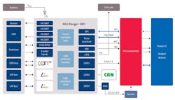
To keep pace with the increasing adoption rate, electronics suppliers are rapidly developing greater levels of chip-level integration to achieve the reduced size, increased reliability, and robust feature sets needed for the next generation of power-lift technologies (Fig. 1). Improvements aren’t limited to bringing discrete technologies into a single package and enhancing existing features. Newer system designs now benefit from simplified development and testing, improved in-vehicle diagnostics, greater system efficiency, and an overall better customer experience.
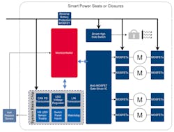
Major system blocks include a microcontroller (providing control, networking, and implementation of the safety concept), power converter, as well as transceivers used for LIN, CAN or CAN-FD. The power control block is protected by a reverse-battery MOSFET. From here, gate drivers link the microcontroller with the power MOSFETs in an H-bridge configuration that offers the required directional and speed control.
Brushed dc motors remain the popular choice, though brushless dc motors (BLDC) offer reduced audible torque noise, higher efficiency, and compact size. Position sensing and localized control buttons, along with supply sensing, round off the design. It is, of course, a given that each device in the motor-drive controller is AEC-100-qualified.
Increased Integration, Reduced Design Complexity
In pursuit of near-silent power-lift operations, automotive engineers are moving away from solutions using electromechanical relays to pure solid-state solutions, eliminating the clicking noise. To that end, Infineon developed multi-MOSFET driver ICs that can be used to replace all relays with N-channel MOSFETs, including the reverse-battery protection circuitry (Fig. 2). The result is silent switching, which isn’t possible with relays.
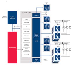
New integrated driver ICs supporting up to 16 N-channel MOSFETs, thus controlling eight half-bridges within a single packaged device, can power up to four dc motors under independent control, or up to seven if a cascading approach is allowed in the design. A similar device for control of up to four half-bridges shares the same package and pinout. A further charge-pump is available to control a reverse-battery MOSFET.
The host microcontroller accesses the driver IC’s functionality via a 24-bit SPI interface. This can also be interfaced with ease to devices that operate with fixed 32-bit frame sizes. In addition, the driver integrates a watchdog function, protection and diagnostics, and an adaptive driver capability. Diagnostics allow all 16 gate drivers to be monitored individually, as well as monitoring of the supply voltage, charge pump voltage, and temperature for both warning and shutdown conditions for the IC.
The multi-MOSFET driver doesn’t compromise on power efficiency. At power on, it immediately starts in its sleep state, drawing less than 8 µA when the enable input is low. In this state, the gate drivers are also off. Once the enable input goes high, the device enters the normal mode state, requiring the watchdog to be regularly serviced unless it’s disabled.
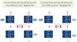
An active free-wheeling control scheme also helps to reduce power losses. Power is typically lost in the free-wheeling MOSFET during pulse-width-modulation (PWM) operation. Active free-wheeling enables the MOSFET associated with the free-wheeling, allowing current to flow through the MOSFET rather than its body diode. This can result in a 4-W power saving (70% duty cycle at 15 A) compared to a passive free-wheeling approach (Fig. 3). It also helps reduce the temperature rise caused by this type of loss in the MOSFETs.
Housed in a 7- × 7-mm VQFN-48 package with an exposed pad, Infineon’s driver supports optical lead tip inspection and offers optimal thermal characteristics. The high level of integration translates to an exceptionally high level of density and cost efficiency with minimal BOM and PCB area for the high number of motors supported.
Variants also are available with permanent motor brake capability that hinders unintentional movement even in sleep mode. This supports an increasingly popular smart closure feature to prevent accidental injury. Moreover, it can be configured to activate in situations of supply overvoltage that result from the motors operating in generator mode.
Ensuring Safety by Diagnosing Failures
A standard integrated safety feature of the driver IC is a watchdog, enabled at power on. During development, it can be disabled by following a process that ensures it can’t be accidentally turned on. In the event of a physical error in SPI communications, such as a shorted signal line, the multi-MOSFET driver enters a fail-safe mode.
Furthermore, the SPI communication is monitored continuously for errors. Detectable errors range from an incorrect number of bits and protocol errors, such as addressing unused addresses, to clock polarity errors or accesses in fail-safe mode that don’t belong to the specified exit sequence. Protection also is enabled when operating in daisy-chain mode. Here the communication with the microcontroller is monitored to ensure that data frames are always a multiple of 8 bits in length.
Ending the Compromise Between Efficiency and EMC
One of the challenges of implementing fully solid-state solutions is achieving an optimal balance between electrical efficiency, keeping losses low, and fulfilling EMC requirements. Optimal load-management techniques and soft start/stop on seats and closures using high-speed PWM signals are common. However, the high-speed transition at load can result in challenges with EMC. This leads to the status quo of making compromises through slew-rate control pins or limited configuration options in registers.
Adaptive MOSFET gate control addresses this with a truly unique level of granularity. Not only is it possible to modify the switching slope without affecting the dead time, preserving the widest range of duty cycles, it also allows differing slew rate for both the ON and OFF cycles. Fully configurable through software via the SPI interface, it allows designers to compensate for the difference in current required between turning a MOSFET on and off. The feature is also “self-adapting,” in that the driver IC recognizes and compensates for lot-to-lot variations of MOSFETs.
Quick Response to “Soft” Short Circuits
Another challenge in such motor-control applications is differentiation between failure cases. Shorts to ground or battery, or the case of open load, ideally need to be detected before turning on the MOSFETs. Next, there’s the challenge to determine the difference between hard short circuits and soft short circuits. The latter appear as higher-than-normal current draw caused by motor problems or wiring harness issues, but they’re not high enough to trigger typical short-circuit protections.
In the driver ICs discussed in this article, these conditions are handled by two features. The first involves the integrated pull-up and pull-down current sources that detect shorts to battery or ground, as well as the open load case. The second feature makes use of integrated current-sensing op amps. These are configurable, making it possible to define a “soft short-circuit” threshold. Thus, the device can respond independently to such failures as well as hard short-circuits in a matter of microseconds. This can be significantly faster than waiting for the host microcontroller to recognize the failure and respond by software, and may enable the downsizing of the MOSFETs.
Sensing of the drain voltage of the high-side MOSFETs can be configured in many different ways, even when the motors are cascaded. For example, in a six-motor configuration, high-side shunt resistors may be implemented to monitor two groups of three motors. Alternatively, the shunt resistors could be placed in series to the two groups of motors. In a four-motor configuration controlled by eight half-bridges, monitoring in both the high and low side also can be used.
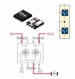
Even with precise layout and assembly, the dual 40-V MOSFETs typically used to configure half-bridges on a system power supply may exhibit stray inductance in PCB traces that must be controlled with external filtering components. Newly available dual MOSFETs (Fig. 4) are wired internally in a half-bridge configuration in a single package, thus reducing layout issues and required external filters.
System Basis Chip to Round Off the Implementation
The power-management and internal communication bus transceivers illustrated in Figure 1 are commonly implemented today in system basis chips (SBCs). A typical device (Fig. 5) provides three low-dropout voltage regulators (LDOs) for the microcontroller, transceivers, and sensors used. It also features a CAN-FD transceiver and up to two LIN transceivers that conform to the latest automotive standards and OEM requirements. In addition, there are devices that support Partial Networking (PN).
Rounding out the feature set are a pair of high-voltage general-purpose I/Os (GPIOs) and high-side outputs implemented to supply LEDs, off-board sensors, or switch inputs. Low quiescent current contributes to the overall efficiency of the system design, with typical draw of in the range of 15 µA in sleep mode to 19.7 µA when WAKE via both CAN and WK pin (e.g., direct signal from handle/switch) is enabled.
Summary
The combination of multi-MOSFET driver ICs, half-bridge MOSFETs, SBC, and host microcontroller described in this article provides a higher integration and lower-cost solution than implementations of comfort drive control based on current relay-based automotive body controllers.
The approach also reduces much of the heavy lifting on the part of engineers and even functional compromises required in some earlier solid-state designs. Such compromises often have to be made when EMC testing at the final phase of development forces adjustments that impact electrical efficiency, resulting in less-than-optimal performance.
For more on Infineon’s comfort motor drives, including the TLE92108 and TLE92104 multi-MOSFET driver ICs, visit https://www.infineon.com/cms/en/product/power/motor-control-ics/brushed-dc-motor-driver-ics/.
About the Author
Rick Browarski
Product Marketing Manager, Infineon Technologies
Rick Browarski is a Product Marketing Director at Infineon Americas, focusing on motor-drive applications. In 22 years with the company, he has held multiple positions including Field Application Engineer and Product Marketing roles for smart power switches and body and comfort applications.
Prior to joining Infineon, Rick worked at Lear handling body-control modules for European OEMs and at Bosch in the Anti-Lock Brakes (ABS) group. Rick holds a B.S. in Electrical and Computer Engineering from Wayne State University in Detroit, Mich. He’s a lifelong resident of the Detroit Metro Area (Motor City). Prior to becoming an engineer, Rick was a professional musician for 15 years. In his spare time, he continues to play guitar.
Comment About the Article
To join the conversation, and become an exclusive member of Electronic Design, create an account today!

Leaders relevant to this article: