Automotive Backlight Driver Sustains Display Brightness

What you'll learn:
- What are the key features of the MAX25512 white LED backlight driver?
- The three main blocks that form the device.
- Its control capabilities via multiple feedback loops.
Automotive start-stop systems increase fuel economy, but they may challenge the power-delivery system to maintain display brightness during restart. Display illumination can be affected by cold-crank situations, with the engine drawing down the car battery enough to cause the display to turn off and back on.
To address this issue, Maxim Integrated developed the MAX25512, a four-channel white LED backlight driver. The single-chip solution, which integrates a current-mode boost converter and current-sense resistor, eliminates the external MOSFET typically required to drive automotive displays. Additional integration includes an I2C communication interface to display settings and diagnostics, as well as a hybrid dimming function. In total, the part lowers the bill-of-materials cost and trims board space by 30%, according to Maxim.
"Car manufacturers are demanding LED drivers with higher integration to reduce solution cost and PCB area," said Szu-Kang Hsien, director of business management for the Automotive Business Unit at Maxim Integrated. "Maxim Integrated's MAX25512 LED driver provides the highest level of integration and efficiency at 2.2-MHz switching frequency."
The MAX25512 operates down to 3 V on battery input after startup without the addition of a pre-boost converter, protecting the display from power disruptions. Its low input voltage and high 91% efficiency at 2.2-MHz operation drives full, constant brightness.
The IC provides load-dump voltage protection up to 40 V in automotive applications and incorporates three major blocks:
- A dc-dc converter with peak current-mode control to implement a boost or SEPIC-type switched-mode power supply. The SEPIC configuration requires either two inductors or a coupled inductor and a coupling capacitor.
- A 4-channel LED driver with up to 120-mA constant-current sink capability per channel.
- A logic control block.
The device tracks the external pulse-width-modulation (PWM) dimming input. Minimum pulse width is 300 ns. Phase-shifting of the output channels is included as an option to reduce electromagnetic interference (EMI). Optional spread spectrum helps further reduce EMI.
Multi-loop control regulates the peak current in the inductor, and the voltage across the LED current sinks to minimize power dissipation. The internal MOSFET is turned on at the beginning of every switching cycle. The inductor current ramps up linearly until it’s turned off at the peak current level set by the feedback loop. Peak inductor current is sensed internally.
The MAX25512 offers leading-edge blanking to suppress MOSFET switching noise. Leading-edge blanking disables the current limit for a fixed period immediately following MOSFET turn-on. This prevents the initial current spike from triggering the current limit and prematurely terminating the switching cycle.
In addition to a peak current-mode-control loop, the MAX25512 IC has two other feedback loops for control. The converter output voltage is sensed through the BSTMON (boost voltage monitoring) input, which goes to the inverting input of the error amplifier. The other feedback comes from the OUT current sinks. This loop controls the headroom of the current sinks to minimize total power dissipation while still ensuring accurate LED current matching (see figure).
The device tracks the external PWM dimming input on the DIM pin. The minimum pulse width is 300 ns. Phase-shifted dimming of the strings is selectable for lower EMI. The signal on the DIM pin is sampled with a 20-MHz internal clock except when phase-shifting is disabled, in which case the DIM signal controls the OUT outputs directly.
Fault protection in the IC includes cycle-by-cycle current limiting in the PWM controller, dc-dc converter output undervoltage protection, output overvoltage protection, open-LED detection, short-LED detection and protection, and overtemperature shutdown.
Also included is thermal protection. Upon reaching the thermal-shutdown temperature, the device immediately disables so that it can cool. When the junction temperature falls by 17°C, the device is re-enabled and the boost converter performs a soft-start. Both thermal shutdown and shorted-LED faults are automatically cleared when the fault is removed.
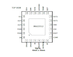
The MAX25512 comes in a compact 24-pin, 4- × 4- × 0.75-mm quad flat no-lead (QFN) package and operates over the temperature range of −40 to +125°C. Both the IC and associated MAX25512EVKIT evaluation kit are available now.
About the Author
Murray Slovick
Contributing Editor
Comment About the Article
To join the conversation, and become an exclusive member of Electronic Design, create an account today!

Leaders relevant to this article: